Water is heated in network heaters, selected steam, in peak hot water boilers, after which the network water enters the supply line, and then to subscriber heating, ventilation and hot water supply units.
Heating and ventilation heat loads unambiguously depend on the outside air temperature tн.в. Therefore, it is necessary to regulate the heat release in accordance with changes in the load. You use mainly central regulation carried out at CHP plants, supplemented by local automatic regulators.
With central regulation, it is possible to apply either quantitative regulation, which is reduced to a change in the flow of network water in the supply line at a constant temperature, or qualitative, in which the flow of water remains constant, but its temperature changes.
A serious disadvantage of quantitative regulation is the vertical misalignment of heating systems, which means an unequal redistribution of heating systems across floors. Therefore, usually high-quality regulation is used, for which the temperature graphs of the heating network for the heating load must be calculated, depending on outside temperature.
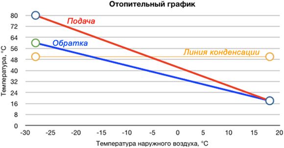
The temperature schedule for the supply and return lines is characterized by the values of the calculated temperatures in the supply and return lines τ1 and τ2 and the calculated outside temperature tn.o. So, a graph of 150-70 ° C means that at a calculated outside temperature tн.o. the maximum (calculated) temperature in the supply line is τ1 = 150 and in the return line τ2 - 70 ° С. Accordingly, the calculated temperature difference is 150-70 = 80 ° C. Lower design temperature of the temperature curve 70 ° C is determined by the need for heating tap water for hot water supply up to tg. = 60 ° C, which is dictated by sanitary standards.
The upper design temperature determines the minimum allowable water pressure in the supply lines, excluding water boiling, and, consequently, the strength requirements, and can vary in a certain range: 130, 150, 180, 200 ° C. An increased temperature schedule (180, 200 ° С) may be required when connecting subscribers according to an independent scheme, which will allow maintaining the usual schedule in the second circuit 150-70 ° C. An increase in the design temperature of the supply water in the supply line leads to a decrease in the consumption of the supply water, which reduces the cost of the heating network, but also reduces the generation of electricity from thermal consumption. The choice of the temperature schedule for the heat supply system must be confirmed by a technical and economic calculation at a minimum of the reduced costs for the CHP and the heating network.
Heat supply to the CHPP-2 industrial site is carried out according to a temperature schedule of 150/70 ° C with a cutoff of 115/70 ° C, in connection with which the temperature of the network water is automatically controlled only up to the outside air temperature "- 20 ° C". Supply water consumption is too high. An excess of the actual flow rate of the heating system over the calculated one leads to an excessive consumption of electrical energy for pumping the coolant. The temperature and pressure in the return pipe does not correspond to the temperature schedule.
The level of heat loads of consumers currently connected to the CHPP is significantly lower than it was envisaged by the project. As a result, CHPP-2 has a thermal capacity reserve exceeding 40% of the installed thermal capacity.
Due to damage to the distribution networks belonging to the TMUP TTS, the discharge from heat supply systems due to the lack of the required pressure drop among consumers and leaks in the heating surfaces of hot water heaters, there is an increased consumption of make-up water at the CHP, exceeding the calculated value by 2.2 - 4, 1 time. The pressure in the return heating main also exceeds the calculated value by 1.18-1.34 times.
The above indicates that the heat supply system for external consumers is not regulated and requires adjustment and adjustment.
Dependence of heating water temperatures on the outside air temperature
Table 6.1.
|
Temperature value |
Temperature value |
||||||||||||
|
Outside air |
filing master ali |
After the elevator |
reverse master |
Outside air |
filing master |
After the elevator |
In back th master ali |
||||||
From a series of articles "What to do if it is cold in the apartment"
What is a temperature graph?
The temperature of the water in the heating system must be maintained depending on the actual temperature of the outside air according to the temperature schedule, which is developed by the heating specialists of the design and power supply organizations for special technique for each source of heat supply, taking into account the specific local conditions. These schedules should be developed based on the requirement that in cold period years in living rooms supported optimum temperature*, equal to 20 - 22 ° С.
When calculating the schedule, heat losses (water temperatures) are taken into account in the area from the heat supply source to residential buildings.
Temperature charts should be drawn up both for the heating network at the exit from the heat supply source (boiler room, CHP), and for pipelines after heating points of residential buildings (groups of houses), that is, directly at the entrance to the heating system of the house.
From heat supply sources in heating network hot water is supplied according to the following temperature curves:*
- from large thermal power plants: 150/70 ° С, 130/70 ° С or 105/70 ° С;
- from boiler houses and small thermal power plants: 105/70 ° С or 95/70 ° С.
* first digit - Maximum temperature direct network water, the second digit is its minimum temperature.
Other temperature curves may apply depending on specific local conditions.
So, in Moscow, at the exit from the main sources of heat supply, schedules of 150/70 ° С, 130/70 ° С and 105/70 ° С (maximum / minimum water temperature in the heating system) are used.
Until 1991, such temperature schedules annually before the autumn-winter heating season were approved by the administrations of cities and other settlements, which was regulated by the relevant regulatory and technical documents (NTD).
Later, unfortunately, this norm disappeared from the NTD, everything was left to the mercy of “caring for the people”, but at the same time, owners of boiler houses, thermal power plants, and other factories - steamers who did not want to miss out on profits.
but regulatory requirement on the compulsory compilation of heating temperature schedules restored Federal Law No. 190-FZ dated July 27, 2010 "On heat supply". That's what FZ-190 is regulated by temperature schedule(the articles of the Law are arranged by the author in their logical sequence):
"... Article 23. Organization of the development of heat supply systems for settlements, urban districts
... 3. Authorized ... bodies [see Art. 5 and 6 FZ-190] must carry out the development, statement and annual update * *
heat supply schemes, which must contain:
…7) Optimal temperature schedule…
Article 20. Checking readiness for the heating season
…5. Heating readiness check the period of heat supply organizations ... is carried out in order to ... the readiness of these organizations to fulfill the schedule of heat loads, maintaining the temperature schedule approved by the heat supply scheme…
Article 6. Powers of bodies local government settlements, urban districts in the field of heat supply
1. The powers of local self-government bodies of settlements, urban districts for the organization of heat supply in the relevant territories include:
... 4) fulfillment of requirements, established by the rules assessing the readiness of settlements, urban districts for the heating season, and readiness control heat supply organizations, heating network organizations, certain categories of consumers to the heating period;
…6) approval of heat supply schemes settlements, urban districts with a population of less than five hundred thousand people ...;
Article 4, paragraph 2. To the powers of the Fed. organ isp. authorities authorized to implement state. heat supply policies include:
11) approval of heat supply schemes for settlements, mountains. districts with a population of five hundred thousand people and more ...
Article 29. Final provisions
…3. Approval of heat supply schemes for settlements ... must be carried out before December 31, 2011 "
And here is what is said about the temperature schedules of heating in the "Rules and Norms for the Technical Operation of the Housing Stock" (approved by the Decree of the State Construction Committee of the Russian Federation of September 27, 2003 No. 170):
“… 5.2. Central heating
5.2.1. System operation central heating residential buildings should provide:
- maintaining the optimal (not lower than the permissible) air temperature in heated rooms;
- maintaining the temperature of the water entering and returning from the heating system in accordance with the schedule of high-quality regulation of the water temperature in the heating system (Appendix N 11);
- uniform heating of all heating devices;
5.2.6. The premises of the operating personnel must contain:
... e) a graph of the temperature of the supply and return water in the heating network and in the heating system depending on the outside air temperature, indicating the operating water pressure at the inlet, static and maximum allowable pressure in the system; ... "
Due to the fact that it is possible to supply a coolant with a temperature not higher than: for two-pipe systems- 95 ° C; for one-pipe - 105 ° C, at heating points (individual house or group for several houses), before water is supplied to the houses, hydroelevator units are installed, in which the direct network water, which has a high temperature, is mixed with cooled return water returning from the heating system of the house. After mixing in the hydraulic elevator, the water enters the house system with a temperature according to the "home" temperature schedule 95/70 or 105/70 ° С.
Below, as an example, is the temperature graph of the heating system after heat point a residential building for radiators according to the top-down and bottom-up scheme (with outside temperature intervals of 2 ° C), for a city with an estimated outside air temperature of 15 ° C (Moscow, Voronezh, Orel):
WATER TEMPERATURE IN DISTRIBUTION PIPELINES, deg. C
AT DESIGNED OUTDOOR AIR TEMPERATURE
|
current outdoor temperature, |
water supply scheme for radiators |
|||
|
"upwards" |
"top down" |
|||
|
serving |
back |
serving |
back |
|
Explanations:
1. In gr. 2 and 4 show the values of the water temperature in the supply pipe of the heating system:
in the numerator - with a calculated drop in water temperature of 95 - 70 ° C;
in the denominator - with a calculated difference of 105 - 70 ° C.
In gr. 3 and 5 show the temperatures of the water in the return pipeline, which coincide in their values at the calculated differences of 95 - 70 and 105 - 70 ° C.
Temperature graph of the heating system of a residential building after the heating point
A source: Rules and regulations technical exploitation housing stock, adj. twenty
(approved by order of the State Construction Committee of the Russian Federation of December 26, 1997 No. 17-139).
Since 2003 there have been "Rules and norms for the technical operation of the housing stock"(approved by the Decree of the State Construction Committee of the Russian Federation of September 27, 2003 No. 170), app. eleven.
|
Current temperature tour outdoor |
Heater design |
|||||||||
|
radiators |
convectors |
|||||||||
|
water supply circuit to the device |
convector type |
|||||||||
|
"top down" |
||||||||||
|
water temperature in distribution pipelines, deg. C |
||||||||||
|
back |
submitter |
back |
submitter |
back |
submitter |
back |
submitter |
back |
||
|
DESIGNED OUTDOOR AIR TEMPERATURE |
||||||||||
The basis for an economical approach to energy consumption in any type of heating system is the temperature schedule. Its parameters indicate the optimal value of water heating, thereby optimizing costs. In order to apply this data in practice, you need to learn more about the principles of its construction.
Terminology
Temperature graph- the optimal value of heating the coolant to create a comfortable temperature in the room. It consists of several parameters, each of which directly affects the quality of the entire heating system.
- Temperature in the inlet and outlet pipes of the heating boiler.
- The difference between these indicators of heating the coolant.
- Indoor and outdoor temperature.
The latter characteristics are decisive for the regulation of the first two. Theoretically, the need to increase the heating of water in the pipes occurs when the temperature outside decreases. But how much needs to be increased so that the heating of the air in the room is optimal? To do this, draw up a graph of the dependence of the parameters of the heating system.
When calculating it, the parameters of the heating system and the residential building are taken into account. For centralized heating, the following temperature parameters of the system are adopted:
- 150 ° C / 70 ° C. Before entering the users, the coolant is diluted with water from the return pipe to normalize the entering temperature.
- 90 ° C / 70 ° C. In this case, there is no need to install equipment for mixing streams.
According to the current parameters of the system, utilities must monitor compliance with the heating medium heating value in the return pipe. If this parameter is less than normal, it means that the room is not warming up properly. The excess indicates the opposite - the temperature in the apartments is too high.
Temperature schedule for a private house
The practice of drawing up a similar schedule for autonomous heating not strongly developed. This is due to its fundamental difference from the centralized one. Regulation of the temperature of the water in the pipes can be carried out in manual and automatic modes. If, during the design and practical implementation, the installation of sensors for automatic regulation of the boiler and thermostats in each room was taken into account, then there will be no urgent need to calculate the temperature schedule.
But for calculating future expenses depending on weather conditions, it will be irreplaceable. In order to draw up it according to the current rules, the following conditions must be taken into account:

Only after these conditions are met, it is possible to proceed to the calculation part. Difficulties may arise at this stage. The correct calculation of an individual temperature graph is a complex mathematical scheme that takes into account all possible indicators.
However, to facilitate the task, there are already ready-made tables with indicators. Below are examples of the most common operating modes of heating equipment. The following input data were taken as initial conditions:
- The minimum air temperature outside is 30 ° С
- The optimum room temperature is + 22 ° С.
Based on these data, schedules were compiled for the following types of heating systems operation.

It is worth remembering that these data do not take into account the design features of the heating system. They only show the recommended values of temperature and power of heating equipment, depending on weather conditions.
The supply of heat to the room is associated with the simplest temperature schedule. The temperature values of the water supplied from the boiler room do not change in the room. They have standard values and range from + 70 ° C to + 95 ° C. Such a temperature schedule for the heating system is the most demanded.
Adjusting the air temperature in the house
District heating is not available everywhere in the country, so many residents install independent systems. Their temperature schedule is different from the first option. In this case, the temperature readings are significantly reduced. They depend on the efficiency of modern heating boilers.
If the temperature reaches + 35 ° C, then the boiler will operate at maximum power. It depends on the heating element, where thermal energy can be sucked in by flue gases. If the temperature values are greater than + 70 ºС, then the boiler performance decreases. In this case, in his technical characteristics the efficiency is 100%.
Temperature schedule and its calculation
How the graph will look depends on the outside temperature. The more negative the outside temperature, the more heat loss. Many do not know where to get this indicator from. This temperature is prescribed in regulatory documents. The temperatures of the coldest five-day week are taken as the calculated value, and the lowest value in the last 50 years is taken.
 Outside and inside temperature graph
 The graph shows the dependence of the outside and inside temperature. Let's say the outside air temperature is -17 ° C. Drawing a line up to the intersection with t2, we get a point characterizing the water temperature in the heating system.
Thanks to the temperature schedule, the heating system can be prepared even for the most severe conditions. It also reduces material costs for installing a heating system. Considering this factor from the point of view of mass construction, the savings are significant.
inside premises depends from temperature coolant, a also others factors:
- Outside air temperature. The smaller it is, the more negatively it affects heating;
- Wind. When there is strong wind heat loss increases;
- The indoor temperature depends on the thermal insulation of the building's structural elements.
Over the past 5 years, the principles of construction have changed. Builders add value to a home by insulating elements. As a rule, this applies to basements, roofs, foundations. These expensive measures subsequently allow residents to save on the heating system.
 Heating temperature graph
 The graph shows the dependence of the outdoor and indoor temperature. The lower the outdoor temperature, the higher the temperature of the heating medium in the system.
The temperature schedule is developed for each city during the heating season. In small settlements a temperature schedule of the boiler room is drawn up, which provides required amount coolant to the consumer.
Change temperature schedule can several ways:
- quantitative - characterized by a change in the flow rate of the coolant supplied to the heating system;
- high-quality - it consists in regulating the temperature of the coolant before supplying it to the premises;
- temporary - a discrete method of supplying water to the system.
The temperature graph is a heating pipe graph that distributes the heating load and is controlled by centralized systems. There is also an increased schedule, it is created for a closed heating system, that is, to ensure the supply of hot coolant to the connected objects. When using an open system, it is necessary to adjust the temperature schedule, since the coolant is consumed not only for heating, but also for household water consumption.
The temperature graph is calculated according to simple method. Hto build it, are necessary initial temperature air data:
- outdoor;
- in room;
- in the supply and return pipelines;
- at the exit from the building.
In addition, you should know the nominal heat load... All other coefficients are standardized by reference documentation. The system is calculated for any temperature schedule, depending on the purpose of the room. For example, for large industrial and civil objects, a schedule of 150/70, 130/70, 115/70 is drawn up. For residential buildings, this figure is 105/70 and 95/70. The first indicator shows the supply temperature, and the second shows the return temperature. The calculation results are entered into a special table, which shows the temperature at certain points of the heating system, depending on the outside air temperature.
The main factor in calculating the temperature graph is the outside air temperature. The calculation table should be drawn up so that the maximum values of the temperature of the coolant in the heating system (schedule 95/70) provide heating of the room. Indoor temperatures are stipulated by regulations.
heating appliances
 Heating device temperature
 The main indicator is the temperature of the heating devices. The ideal temperature schedule for heating is 90/70 ° C. It is impossible to achieve such an indicator, since the temperature inside the room should not be the same. It is determined depending on the purpose of the room.
In accordance with the standards, the temperature in the corner living room is + 20 ° C, in the rest - + 18 ° C; in the bathroom - + 25 ° C. If the outside air temperature is -30 ° C, then the indicators increase by 2 ° C.
except Togo, exists norms for others types premises:
- in rooms where children are - + 18 ° C to + 23 ° C;
- children's educational institutions - + 21 ° C;
- in cultural institutions with mass attendance - + 16 ° C to + 21 ° C.
This temperature range is compiled for all types of rooms. It depends on the movements performed inside the room: the more there are, the lower the air temperature. For example, in sports facilities, people move a lot, so the temperature is only + 18 ° C.
 Indoor air temperature
 Exists certain factors, from which depends temperature heating appliances:
- Outside air temperature;
- Heating system type and temperature difference: for single pipe system- + 105 ° С, and for one-pipe - + 95 ° С. Accordingly, the differences in for the first area are 105/70 ° C, and for the second - 95/70 ° C;
- The direction of supply of the coolant to the heating devices. At the top supply the difference should be 2 ºС, at the lower one - 3 ºС;
- Type of heating devices: heat transfer is different, therefore the temperature schedule will differ.
First of all, the temperature of the coolant depends on the outside air. For example, outside the temperature is 0 ° C. Wherein temperature regime in radiators it should be equal to 40-45 ° С on the supply, and 38 ° С on the return line. At air temperatures below zero, for example, -20 ° C, these indicators change. In this case, the flow temperature becomes 77/55 ° C. If the temperature indicator reaches -40 ° C, then the indicators become standard, that is, on the supply + 95/105 ° C, and on the return - + 70 ° C.
Additional options
In order for a certain temperature of the coolant to reach the consumer, it is necessary to monitor the state of the outside air. For example, if it is -40 ° C, the boiler room must supply hot water with an indicator of + 130 ° C. Along the way, the coolant loses heat, but still the temperature remains high when it enters the apartments. Optimal value+ 95 ° C. To do this, an elevator unit is mounted in the basements, which serves for mixing hot water from the boiler room and heat carrier from the return pipeline.
Several institutions are responsible for the heating main. The boiler house monitors the supply of hot coolant to the heating system, and the state of the pipelines is monitored by city heating networks. The housing office is responsible for the elevator element. Therefore, in order to solve the problem of supplying the coolant to new house, you need to contact different offices.
Installation of heating devices is carried out in accordance with regulatory documents. If the owner himself replaces the battery, then he is responsible for the functioning of the heating system and changing the temperature regime.
Adjustment methods
 Dismantling the elevator unit
 If the boiler room is responsible for the parameters of the coolant leaving the warm point, then the employees of the housing office should be responsible for the temperature inside the room. Many tenants complain about the coldness in their apartments. This is due to the deviation of the temperature graph. In rare cases, it happens that the temperature rises by a certain value.
Heating parameters can be adjusted in three ways:
- Reaming the nozzle.
If the temperature of the coolant at the supply and return is significantly underestimated, then it is necessary to increase the diameter of the elevator nozzle. Thus, more liquid will pass through it.
How can this be done? To begin with, shutoff valves are closed (house valves and taps on elevator unit). Next, the elevator and nozzle are removed. Then it is reamed by 0.5-2 mm, depending on how much it is necessary to increase the temperature of the coolant. After these procedures, the elevator is mounted in its original place and put into operation.
To ensure sufficient tightness of the flange connection, it is necessary to replace the paronite gaskets with rubber ones.
- Suction suppression.
In extreme cold, when the problem of freezing of the heating system in the apartment arises, the nozzle can be completely removed. In this case, the suction can become a jumper. To do this, it is necessary to drown it with a steel pancake, 1 mm thick. Such a process is carried out only in critical situations, since the temperature in pipelines and heating devices will reach 130 ° C.
- Differential adjustment.
In the middle of the heating season, a significant rise in temperature can occur. Therefore, it is necessary to regulate it using a special valve on the elevator. To do this, the supply of hot coolant is switched to the supply line. A pressure gauge is mounted on the return line. The regulation is carried out by closing the valve on the supply pipeline. Next, the valve opens slightly, while the pressure should be monitored using a pressure gauge. If you just open it, then there will be a drawdown of the cheeks. That is, an increase in the pressure drop occurs in the return pipeline. Every day, the indicator increases by 0.2 atmosphere, and the temperature in the heating system must be constantly monitored.
Heat supply. Video
How is the heat supply of private and apartment buildings, can be found in the video below.
When drawing up a heating temperature schedule, various factors must be taken into account. This list includes not only the structural elements of the building, but the outside temperature, as well as the type of heating system.
In contact with
What patterns obey the changes in the temperature of the coolant in central heating systems? What is it - the temperature graph of the heating system 95-70? How to bring the heating parameters in line with the schedule? Let's try to answer these questions.
What it is
Let's start with a couple of abstract theses.
- With a change in weather conditions, the heat loss of any building changes after them... In freezing conditions, in order to maintain a constant temperature in an apartment, much more heat energy is required than in warm weather.
Let's clarify: heat consumption is determined not by the absolute value of the air temperature outside, but by the delta between the street and the interior.
So, at + 25C in the apartment and -20 in the yard, the heat costs will be exactly the same as at +18 and -27, respectively.
- The heat flux from the heater at a constant temperature of the coolant will also be constant.
A drop in temperature in the room will slightly increase it (again, due to an increase in the delta between the coolant and the air in the room); however, this increase will be categorically insufficient to compensate for the increased heat loss through the building envelope. Simply because the current SNiP limits the lower temperature threshold in the apartment to 18-22 degrees.
An obvious solution to the problem of increasing losses is to increase the temperature of the coolant.
Obviously, its growth should be proportional to the decrease in outdoor temperature: the colder it is outside the window, the greater the heat loss will have to be compensated. Which, in fact, brings us to the idea of creating a certain table of agreement of both values.
So the graph temperature system heating is a description of the dependence of the temperatures of the supply and return pipelines on the current weather outside.
How it works
There are two different types charts:
- For heating networks.
- For indoor heating system.

To clarify the difference between the two, it is probably worth starting with a short excursion how central heating works.
CHP - heating networks
The function of this bundle is to heat the coolant and deliver it to the end consumer. The length of heating mains is usually measured in kilometers, the total surface area is in thousands and thousands square meters... Despite the measures for thermal insulation of pipes, heat losses are inevitable: after passing the way from the CHP or boiler house to the border of the house, the process water will have time to partially cool down.
Hence - the conclusion: in order for it to reach the consumer, while maintaining an acceptable temperature, the supply of the heating main at the exit from the CHPP should be as hot as possible. The boiling point is the limiting factor; however, with increasing pressure, it shifts towards an increase in temperature:
| Pressure, atmospheres | Boiling point, degrees Celsius |
| 1 | 100 |
| 1,5 | 110 |
| 2 | 119 |
| 2,5 | 127 |
| 3 | 132 |
| 4 | 142 |
| 5 | 151 |
| 6 | 158 |
| 7 | 164 |
| 8 | 169 |
Typical pressure in the supply pipe of the heating main is 7-8 atmospheres. This value, even taking into account the head loss during transportation, allows you to start heating system in houses up to 16 storeys high without additional pumps. At the same time, it is safe for routes, risers and connections, mixer hoses and other elements of heating and hot water systems.

With a certain margin, the upper limit of the flow temperature is taken equal to 150 degrees. The most typical heating temperature curves for heating mains lie in the range 150/70 - 105/70 (flow and return temperatures).
House
There are a number of additional limiting factors in a home heating system.
- The maximum temperature of the coolant in it cannot exceed 95 C for a two-pipe and 105 C for.
By the way: in preschool educational institutions the restriction is much stricter - 37 C.
The price of lowering the supply temperature is an increase in the number of radiator sections: in the northern regions of the country, the premises of groups in kindergartens are literally surrounded by them.

- For obvious reasons, the delta of temperatures between the supply and return pipelines should be as small as possible - otherwise the temperature of the batteries in the building will vary greatly. This implies fast circulation of the coolant.
However, too fast circulation through the house heating system will lead to the fact that the return water will return to the line with an exorbitant high temperature, which is unacceptable due to a number of technical limitations in the operation of the CHPP.
The problem is solved by installing one or several elevator units in each house, in which the return flow is added to the stream of water from the supply pipeline. The resulting mixture, in fact, ensures the rapid circulation of a large volume of the coolant without overheating the return pipeline of the route.

For in-house networks, a separate temperature schedule is set, taking into account the operation of the elevator. For two-pipe circuits a typical heating temperature schedule is 95-70, for one-pipe (which, however, is rare in apartment buildings) - 105-70.
Climatic zones
The main factor that determines the scheduling algorithm is the estimated winter temperature. The table of coolant temperatures should be drawn up in such a way that the maximum values (95/70 and 105/70) at the frost peak provide the corresponding SNiP temperature in the living quarters.
Let's give an example of an in-house schedule for the following conditions:
- Heating devices - radiators with heating agent supply from bottom to top.
- Heating - two-pipe, with.

- The design temperature of the outside air is -15 C.
| Outside air temperature, С | Feed, С | Return, С |
| +10 | 30 | 25 |
| +5 | 44 | 37 |
| 0 | 57 | 46 |
| -5 | 70 | 54 |
| -10 | 83 | 62 |
| -15 | 95 | 70 |
Nuance: when determining the parameters of the route and the internal heating system, the average daily temperature is taken.
If it is -15 at night and -5 in the daytime, -10C appears as the outside temperature.
And here are some calculated values winter temperatures for the cities of Russia.
| Town | Design temperature, С |
| Arkhangelsk | -18 |
| Belgorod | -13 |
| Volgograd | -17 |
| Verkhoyansk | -53 |
| Irkutsk | -26 |
| Krasnodar | -7 |
| Moscow | -15 |
| Novosibirsk | -24 |
| Rostov-on-Don | -11 |
| Sochi | +1 |
| Tyumen | -22 |
| Khabarovsk | -27 |
| Yakutsk | -48 |

In the photo - winter in Verkhoyansk.
Adjustment
If the management of the CHP and heating networks is responsible for the parameters of the route, then the responsibility for the parameters of the in-house network rests with the housing dwellers. A very typical situation is when, when residents complain about the cold in apartments, measurements show deviations from the schedule to the lower side. Slightly less often, it happens that measurements in the wells of thermal workers show an overestimated return temperature from the house.
How to bring the heating parameters in line with the schedule with your own hands?
Reaming the nozzle
With an underestimated mixture and return temperature, the obvious solution is to increase the diameter of the elevator nozzle. How it's done?
The instruction is at the service of the reader.
- All valves or valves in the elevator unit (entrance, house and hot water supply) are closed.
- The elevator is dismantled.
- The nozzle is removed and reamed out by 0.5-1 mm.
- The elevator is assembled and started up with air purging in the reverse order.
Tip: instead of paronite gaskets, you can put rubber ones on the flanges, cut to the size of the flange from the car camera.

An alternative is to install an elevator with an adjustable nozzle.
Suction suppression
In a critical situation (extreme cold and freezing apartments) the nozzle can be completely removed. To prevent the suction from becoming a jumper, it is muffled by a pancake made of steel sheet with a thickness of at least a millimeter.

Attention: this is an emergency measure used in extreme cases, since in this case the temperature of the radiators in the house can reach 120-130 degrees.
Differential adjustment
At elevated temperatures as a temporary measure until the end heating season the adjustment of the elevator differential with a gate valve is practiced.
- The DHW is switched over to the flow line.
- A pressure gauge is installed on the return line.
- The inlet valve on the return pipe is completely closed and then gradually opened with pressure control according to a manometer. If you simply close the valve, the slump of the cheeks on the stem can stop and defrost the circuit. The difference is reduced by increasing the pressure on the return line by 0.2 atmospheres per day with daily temperature control.
