How to work with metal tiles correctly? This important question is asked by almost every developer who has chosen this modern, durable and very practical material for their roof.
We will tell you in detail how to properly install metal tiles, following all the recommendations of its manufacturers. We will also tell you which of the installation schemes will be more effective, and which installation scheme for the tiles is more effective.
In addition to all this, you will be able to learn how the roofing "pie" is made and what tools and materials you will need in construction and many other aspects. We really hope that instructions for installation work with metal tiles will be necessary not only for an ordinary developer, but also for a professional builder, regardless of the scale of your roof construction.
Installation technology
Brief information about the roofing "pie":
At the very beginning of the installation work with metal tiles (you can download the training video file or just watch it a little below), remember some basic concepts and schemes of roofing "pies". He earned this name because of the decent number of layers that perform their special functions.
It is these components, with the correct and rational selection of the necessary materials, will provide you with a reliable and durable roof over your head.
It does not matter at all who will perform the work, you yourself or a specially hired team of skilled workers, you must clearly understand that the roof is a very complex system with many nuances and details and here it is necessary to follow all recommendations from manufacturers and general construction standards for the installation of metal tiles pretty strict.
As the owner, you are simply obliged to constantly keep the installation of metal tiles under your strictest control (you can download the training video file or just watch it here), since the negative consequences of poor-quality work may not appear immediately.
For example, if the steam or waterproofing components are poorly placed, then the steam can condense into a liquid, and your roof will simply slowly rot. Remember that for a good and durable installation, you must take into account all the requirements for the installation of metal tiles.
Installation of the main elements of the roof
- Rafter systems.
- Counter-rail.
- Waterproofing film.
- Beam for vertical lathing.
- The first timber for the horizontal lathing.
- Beam for horizontal lathing.
- Additional crate.
- Wind board.
- Gutter bracket.
- Curtain rail.
- Metal tiles.
- Roofing ridge.
- Ridge seal.
- Dormer window.
- Special thermal insulation.
- Vapor barrier film.
- Attic filing.
Step-by-step installation instructions (Monterrey or equivalent)
Tools and special equipment
 Working with Monterrey tiles or their analogues must be started with special preparation of tools. This is useful for you:
- Tools for cutting sheet metal tiles.
- Screwdriver (preferably one that runs on a battery).
- Small hammer.
- Rail. Desirably flat and long. You will use it as a rule.
- Markers.
It is recommended to use a special tool for cutting metal tiles.
1. scissors for cutting metal (electric or manual).
2. hacksaws or electric reciprocating saws with an appropriate blade.
3. electric cutting shears.
4. Electric jigsaws.
5.Circular saw with teeth from Pobedit.
After completion of work, it is required to carefully remove metal shavings and sawdust. This is done specifically so that when rusting, they could not spoil the anti-corrosion coating that is applied to the metal tile.
Attention! Do not cut metal tiles with tools with an abrasive wheel. For example, using a grinder. Otherwise, when exposed to high temperatures on the metal tile, not only the protective polymer layer, but also a special anti-corrosion zinc coating can be destroyed.
Because of this, very rapid corrosion will start on the tiles and rust stains will start in your roof.
Installation in steps:
 1.
The initial step is that the rafters under the metal tile should be in the range of 550-900 mm.
1.
The initial step is that the rafters under the metal tile should be in the range of 550-900 mm.
Remember that after your purchase of insulation boards, the pitch of the rafters will depend on the width of the boards. In the future, the insulation must be inserted immediately between the rafters in the roof. As the main material for the rafter system, you can choose a bar with dimensions of 150 by 50 mm.
After installing the rafters, a control measurement of the ramp is required. You also need to check the flatness and squareness of the entire structure. For these purposes, you need to measure the diagonal dimensions in the slopes.
If you find a slight deviation of no more than 10 mm, then you can hide them yourself with the help of special components.
 2.
Please note that if you are using metal tiles for your roof, then the mandatory slope for the slope must correspond to an angle of 14 °.
2.
Please note that if you are using metal tiles for your roof, then the mandatory slope for the slope must correspond to an angle of 14 °.
The length of the sheet is determined by the main size - this will be the length of the slope. It is measured from the beginning of the ridge to the end of the eaves, taking into account the eaves overhang. The overhang size is at least 40 mm.
If you are going to make a ramp on the roof more than 6 meters, then you will need to break the sheets into several pieces. These pieces will overlap.
You need to overlap about 15 cm. If you use long sheets in the installation, then you will get smaller joints, but it is more difficult to lay them.
 3.
As a result of daily temperature fluctuations, condensation can collect on the lower surfaces of the tiles. Condensation can also be produced by warm air, which gets from the house itself into the space under the roof.
3.
As a result of daily temperature fluctuations, condensation can collect on the lower surfaces of the tiles. Condensation can also be produced by warm air, which gets from the house itself into the space under the roof.
Due to excess moisture, the insulation is excessively saturated with water and, as a result, its properties become sharply worse. In the future, your roof can completely freeze and form ice on the tiles themselves. The rafters can rot and mold can develop indoors.
In order for you to be able to avoid all the negative moments when installing metal tiles, you will need insulation of the correct thickness.
In addition to all this, the technologies used in the installation of metal roofing imply protection for insulation and the use of waterproofing and vapor barrier.
A space of about 40 mm will be sufficient for good ventilation. A small gap can be left on the eaves overhang, and small holes must be cleared for the rubber seal.
 4.
Roll out the waterproofing strictly horizontally over the entire surface of the rafters. Start at the edge of the eaves and add 20mm weight gain.
4.
Roll out the waterproofing strictly horizontally over the entire surface of the rafters. Start at the edge of the eaves and add 20mm weight gain.
A small overlap is required between the adjacent panel. The optimal overlap size is 15 cm.
The film of the Yutafol and Yutakon brands is located with the side with a colored stripe on the edge, outward. You cannot turn the film over without permission.
You can find a huge number of different types of films in the markets and in hardware stores, but for the right choice, you better ask the manager for advice.
 5.
Together with the installation of waterproofing, you can install roofing from the outside and thermal insulation materials from the inside.
5.
Together with the installation of waterproofing, you can install roofing from the outside and thermal insulation materials from the inside.
It will be better if you install thermal insulation tiles between the rafters themselves.
In this case, you need to leave a small space of 20 mm.
Otherwise, the entire film will lose its properties. If you have purchased Tyvek or Yutavek film, then you do not need to make a gap.
 6.
Attach the para-insulation to the inside of the rafters with a stapler.
6.
Attach the para-insulation to the inside of the rafters with a stapler.
The most popular vapor barrier is "Yutafol H Silver" and "Yutafol H 110".
It is better to overlap the parainsulation sheets.
Use adhesive tape to connect.
After you complete all the work, you can start cladding.
 7.
Perform a crate from a bar that has been treated with an antiseptic. First, you will need to nail in the beams from the top of the waterproofing film, and then fasten the boards for the sheathing.
7.
Perform a crate from a bar that has been treated with an antiseptic. First, you will need to nail in the beams from the top of the waterproofing film, and then fasten the boards for the sheathing.
The lathing boards that you will lay first must be used an order of magnitude thicker than all the others. They should be 10 - 15 mm thicker. After that, you must maintain an even distance between the lathing bars.
When you are working with a high quality material such as Monterrey shingles, you can attach a second timber if the distance from the bottom edge is 300 mm. Measure to the middle of the next board.
For materials "MP Maxi" the indent can be no more than 350 mm.
The distance between the axis in the remaining beams can be from 32mm to 100mm with Monterey tiles and 350mm with Supermonterey tiles and 400mm with Maxi.
You can work with battens of slightly longer lengths if the pitch is 1000 mm.
Perform continuous battens near the chimney and dormer. You can nail individual planks on both sides of the ridge, but you will need to raise the end strips above the level of the regular battens. To a height no more than the profile of the tile itself.
 8.
Before installing the shingles, you will need to secure the bottom plank at the valley at the inner joint at the ramp. Fasteners can be made using a simple self-tapping screw.
8.
Before installing the shingles, you will need to secure the bottom plank at the valley at the inner joint at the ramp. Fasteners can be made using a simple self-tapping screw.
If you need to do the joining of the planks, then make a small overlap of 100 - 150 mm. After that, you will need to mark and trim the tiles. Correct installation of the tiles (photo on the left) must be done from the bottom and up.
You will need to install the valley strip on top of the very junction of the sheets.
Attention! The abutment node is the most vulnerable point of the roof. In the suppression, repair of metal tiles and the entire roofing system, you are strongly advised to approach issues related to installation work, especially carefully
 9.
In order to ensure tightness in the junction of the tiles to the chimney or walls on the slopes, you can make an apron from the inside. For its construction, you can take the lower abutment bars. Lean the block against the wall and mark the block on the brick. You will then be able to punch the strobe using the grinder on the line you marked. Then you need to remove dust from the wall and, if possible, wash it with water.
9.
In order to ensure tightness in the junction of the tiles to the chimney or walls on the slopes, you can make an apron from the inside. For its construction, you can take the lower abutment bars. Lean the block against the wall and mark the block on the brick. You will then be able to punch the strobe using the grinder on the line you marked. Then you need to remove dust from the wall and, if possible, wash it with water.
It is better to start the installation of the internal apron from the walls of the pipe, which are located on the lower side of the ramp. Cut the block a little in the right place and fasten it with a self-tapping screw.
Using this algorithm, you will be able to mount the apron around the entire pipe.
When the planks are docked, a small protrusion of 150 mm can be made. After you slide the edge of the apron into the gutter, you will need to cover it with a silicone-based sealant.
Then you will need to put a flat sheet under the bottom edge in the inner apron. This sheet is called a tie.
It will provide a good drain for the water. You can choose the direction of the tie and direct it either down or in the valley. Along the very edge of the tie, you will need to make a small side. It can be done using a regular hammer and pliers.
The tile sheet must be mounted on top of the apron or tie. Once the entire roof covering has been laid around the chimney, you can start working on the outer apron. In working with it, you can use the upper abutment strips.
The installation of the upper strips can be done, as well as the lower ones, only you do not need to wind the upper edge in the groove, but fasten to the wall itself.
Attention: When you move on metal roof tiles, you must strictly follow the rules of personal safety.
You must wear shoes that are soft and comfortable for you. It is worth treading only in the natural deflections of the waves. You should also use the installer's belt and buckle up with a safety rope.
 10.
Fasten the gutter holder to the lowest timber in the crate. Their installation method, step depends on what type of gutter system you will use.
10.
Fasten the gutter holder to the lowest timber in the crate. Their installation method, step depends on what type of gutter system you will use.
It is for this that the operating instructions are given. It is worth paying attention to the edges of the gutters. The edges should be slightly below the edge of the shingle itself.
The offset can be about 25 - 30 mm. This is to prevent your gutter from damaging the snow that comes off the roof in winter.
 11.
If your gutter system has a rectangular cross-section, then the gutters just need to be inserted and fixed in the holders.
11.
If your gutter system has a rectangular cross-section, then the gutters just need to be inserted and fixed in the holders.
The eaves planks are attached to the roof batten, with the lower edges of the planks overlapping the edges of the gutters. The waterproofing film is taken out above the eaves itself (in order to drain the condensates).

If you are installing a gutter with round sections, then it is worth bringing in the rear edge of the protrusion itself for fixing. The installation of the eaves plank is performed according to the technology described above.
When installing gutters with a circular cross-section, it is necessary to bring its rear edge into the fixed protrusion of the holder.
The cornice planks are set slightly higher than indicated.
The roofing film is taken out over the eaves.
Instructions for the manufacture of roof windows
 12.
It is worth making a small indent and considering roof options using skylights. The number of your windows, which is necessary for the desired level of light in the attic, can be easily determined by the ratio of useful glazing areas to the area of the room itself.
12.
It is worth making a small indent and considering roof options using skylights. The number of your windows, which is necessary for the desired level of light in the attic, can be easily determined by the ratio of useful glazing areas to the area of the room itself.
Better to start at 1: 8 and work up to 1:12. If your attic has an area of about 100 m2, then the total area of all windows can be about 10 m2.
 Installation of roof windows is recommended to be done at a height of about 90-110 cm above floor level. It is worth considering that several small windows will give your attic more sunlight than one huge window.
In addition to all this, you can install entire groups of roof windows - horizontal, vertical or combined. Usually, the windows are installed on the crate itself, but it is worth fixing them directly to the rafters with self-tapping screws.
The openings for the window itself should exceed its overall dimensions by about 40-60 mm horizontally and 45 mm vertically. Usually, installing windows in the attic will not cause you any difficulty.
 13.
The first sheets are leveled along the edge of the end of the roof and fixed from above with a self-tapping screw. It is worth making a visor at the cornice of about 40 mm.
13.
The first sheets are leveled along the edge of the end of the roof and fixed from above with a self-tapping screw. It is worth making a visor at the cornice of about 40 mm.
Connect the sheets with self-tapping screws from above from overlaps. Do not fix them tightly to the lathing bars. It is better to let them move freely relative to the screw. (fig. B).
Next is the third sheet of tile, which is laid according to the technology of the second. Next, you need to align all three sheets with the cornice and place them parallel. If you need to join sheets in length, then it is worth laying them in the order shown in Figure B.
 14.
The lower part of the sheets is attached to self-tapping screws in the bottom of the shingle wave.
14.
The lower part of the sheets is attached to self-tapping screws in the bottom of the shingle wave.
The fastening step is through one wave. The next row of the self-tapping screw must be arranged in the order of the checkerboard.
It is required to alternate after one wave.
The side overlap of the sheet must be fastened with a self-tapping screw for each ridge.
For installation work, you can spend about 6 - 8 self-tapping screws per square meter.
 15.
At the end of the roof, install end strips with an overlap of 50 mm.
15.
At the end of the roof, install end strips with an overlap of 50 mm.
They should be fixed with self-tapping screws almost every 550 - 600 mm.
At the very top, you better use self-tapping screws with a length of about 80 mm. If necessary, then feel free to cut the planks.
 16.
Skating bars can be flat or completely round.
16.
Skating bars can be flat or completely round.
It is worth installing a bar for round skates with the fact that you install plugs on it.
The shape is selected individually for each roof. For flat skates, plugs are not needed at all.
 17.
You can put a curly seal under your skate, but free all the holes for ventilation in advance.
17.
You can put a curly seal under your skate, but free all the holes for ventilation in advance.
Flat or round ridge skates can be installed on the already installed seal.
The self-tapping screws for the ridge are about 80 mm long and are located through one wave.
The overlap between the ridge panel is about 100 mm.
Antenna output mounting
 18.
Before the installation itself, it is required to cut off the entire upper part of the antenna outlet and leave the diameter slightly less than the diameter of the antenna pole.
18.
Before the installation itself, it is required to cut off the entire upper part of the antenna outlet and leave the diameter slightly less than the diameter of the antenna pole.
Then the antenna output is installed on the rack using a mallet, thereby achieving a repetition of the contours of the roof.
The joints should be coated with silicone glue and attached to the screws.
Installation work with a ventilation element
 19.
At the very beginning, you need to mark and cut a neat hole in the shingles.
19.
At the very beginning, you need to mark and cut a neat hole in the shingles.
Insert ventilation into the passage, carefully level the level and fasten it to the self-tapping screw.
If you are making a hood from your home, then use a regular tube, which you will attach to the roofing pie with ordinary tape.
Installation of stairs
20. to install the ladder, use the bracket (4 pcs. per section). Put them on the racks in the stairs and fix them with self-tapping screws. It is better to fasten the tiles in the deflections of the waves to the roofing surface itself.

In the place where the brackets border, you can make a seal. Your ladder should be chosen according to the number of ramps on the roof in small sections. The section that will be from the very top must be attached using a special bracket.
Installation and installation of roof barriers
 21.
For complete safety in the maintenance of your roof at the level of the eaves, you need to install the grating vertically.
21.
For complete safety in the maintenance of your roof at the level of the eaves, you need to install the grating vertically.
In these cases, the lathing must be completed with a continuous layer. Supports for fences are installed in the deflections of the wave of the tile itself.
It fixes the bracket through a special rubber gasket, while using only screws coated with a zinc layer. The support spacing is approximately 900 mm.
Adjust your supports to the slope of the roof and secure them carefully.
Then you need to hang the special roof rails on the supports that you installed. At the junctions of the fence sections and the supports, you need to drill holes in (12 mm at the top of the crossbar and 10 mm at the bottom of the crossbar), through these holes you will connect your sections to the supports.
You will need to cover all the holes at the top of the crossbars with polyethylene plugs. After the entire assembly is completed, then you need to seal all the joints.
Installation and installation of transition bridges
 22.
For comfortable control and maintenance of chimneys, television antennas and many other elements, special bridges for crossings have long been provided on the roof.
22.
For comfortable control and maintenance of chimneys, television antennas and many other elements, special bridges for crossings have long been provided on the roof.
These elements are best mounted on a solid sheathing layer. All support brackets for the bridge are fastened using the technology with the fastening of the support fence.
The slope of the platforms is adjusted by selecting the number of holes in the bracket mounting. It is better to fix these platforms with M8x20 bolts. Better not to spare and place a couple of bolts on each side of the platform.
Installation of snow guards on a metal roof
 23.
In order to protect yourself from snow falls, like small avalanches, you can install simple and convenient snow holders. The lathing bars should be solid under them.
23.
In order to protect yourself from snow falls, like small avalanches, you can install simple and convenient snow holders. The lathing bars should be solid under them.
The bracket pitch is about 1000mm. The brackets are installed at the end at a distance of 500 mm from the end of the snow holders.
Installation and assembly of snow guards should be carried out at a distance of 350 mm from the edges of the roof eaves.
 If your roof has a slope greater than 8 meters, then you will need an intermediate snow barrier. Remember that the installation of snow guards above the windows is required.
From the point of view of economy, you can cheat and use a metal tile bar as a snow guard. This bar can be easily attached to the bottom of the wave using ordinary self-tapping screws.
Correct grounding of the roof
In order to protect your roof from lightning strikes, it is necessary to perform lightning protection.

You can use a variety of lightning rods. Mesh, rod or cable. Your choice must be correct and based on many factors.
The figures show the classic options of protection, where 1 - lightning rod, 2 - drop, 3 - grounding loops, 4 - current conductor.
Special features of installation work with other types:


As can be seen from the figures (in order to enlarge you need to click), installation work with the "Cascade" metal tile is carried out on the crate with steps different from the steps of the "Monterey" or "Elite" tiles.
All these differences are caused by different profile sizes.
Installation work with Andalusia tiles with special Z-locks also has its own quirks. A special perforation is made in the part of the lock for this type of tile. This greatly simplifies the placement and work of fixing the shingles on the roof. The mounts remain hidden.
Thanks to this trick, the entire roof looks monolithic.
How to cover the roof - video instruction
When buying materials - check with suppliers all the important points regarding the technology of installation work with this type of product.
Only by strictly following all these rules, you will have a durable and beautiful roof over your head.
Metal tiles are a reliable and durable roof covering. The high corrosion resistance of this material is ensured through the use of high quality raw materials (galvanized steel from the world's leading manufacturers) and special polymer coatings. In the Stroymet company you can buy. We also stock roofing materials from other well-known manufacturers from Russia and Finland.
Additional elements of metal tiles Grand Line
 |
Fixes sheets of metal tiles at the ends of roof slopes, preventing loosening of fasteners. Protects the structure from wind and precipitation. |
 |
Upper valley plank A decorative element that covers the joint between the slopes at the inner corners of the roof. |
 |
Lower valley plank Provides removal of atmospheric precipitation at the joints of adjacent slopes. |
 |
Prevents uncontrolled snow removal from roof slopes. Protects gutters from additional snow load, as well as the area adjacent to the building. |
 |
Closes the joint of adjacent roof slopes, preventing precipitation from entering the under-roof space. |
 |
It is mounted in the end part of the ridge. |
 |
Protects the frontal board and other wooden elements of the rafter system located at the bottom of the eaves from the negative effects of moisture. |
 |
Abutment bar Installed at the joints of roof slopes with vertical structures (walls, chimneys). |
Basic requirements when working with metal tiles
Shipping
To avoid damage, the sheets must be fixed in the car body. At the same time, they must completely fit in the body along the length (otherwise, bends are possible on the overhang line). The optimal mode of movement of the vehicle: the speed is not higher than 80 km / h, without sudden acceleration and deceleration.
 Loading and unloading works
They can be made manually or using special equipment (forklift trucks, cranes with soft slings). The packages are unloaded onto a flat, clean, dry surface. The number of personnel for manual unloading depends on the length of the sheets (1 person per 2 running meters, but not less than 2 people per 1 sheet). Carrying is carried out in an upright position. It is forbidden to drag sheets along the ground and other surfaces.
Sheets of metal tiles are stacked using wooden blocks (stacked at the base of the stacks) and slats (stacked between the sheets). If storage is carried out in an open area, it is necessary to provide a slight slope of the sheets along the length for water drainage. In the immediate vicinity of the storage place, it is prohibited to carry out welding work, as well as other operations that can damage the surface of the metal tile.
Safety engineering
In order to avoid cuts on sharp edges of metal tiles, personnel must work in protective gloves. In the process of lifting sheets to the roof and installing them, it is necessary to use safety equipment. It is forbidden to carry out high-altitude work in difficult weather conditions (with strong wind, rain, hail, snowfall).
Fasteners
To fix the sheets of metal tiles, self-tapping screws made of stainless steel with a polymer gasket are used. Approximate consumption - 6-7 screws per 1 sq. m.
Tools for the installation of metal tiles Grand Line
|
|
|
|
|
|
|
|
|


Note! When cutting metal tiles, do not use angle grinders with abrasive wheels. Violation of this requirement can lead to intensive corrosion of products (due to damage to the zinc layer and polymer coating).
Roofing cake structure
Modern roofs are made up of several layers with different functions. The reliability and durability of the roof is ensured through the use of high-quality materials and the correct installation of the Grand Line metal tile. If even one element is incorrectly installed, this will lead to a sharp decrease in the service life of the entire structure. According to the experience of Stroymet specialists, a violation of the requirements for laying leads to the accumulation of moisture in the insulation (because of this, its operational characteristics are significantly deteriorated), as well as the destruction of wooden and metal parts (due to decay and corrosion).

- Metal tiles.
- Lathing.
- Waterproofing.
- Rafter leg.
- Counter grill.
- Vapor barrier membrane.
- The first lathing board.
- Gutter bracket.
- Frontal board.
- Dropper.
- Cornice strip.
- Perforated ventilation tape.
Installation of thermal insulation
Fits between the elements of the rafter system. To keep it better, it needs to be cut with a small margin in width (1-1.5 cm). Installation should be organized in such a way as to completely exclude the possibility of moisture ingress into the thermal insulation layer.

Installation of vapor-waterproofing films and membranes
Insulation materials are laid on both sides of the rafter structure: outside - waterproofing, inside - vapor barrier. Laying is done horizontally, from bottom to top, with an overlap of 15-20 cm.

Standard waterproofing is installed with 2 ventilation gaps of 3-5 cm:
- between the film and the heat-insulating layer;
- between the film and the roof covering.
The Super Diffusion Membrane is installed with 1 gap (between the membrane and the roof covering). A second gap is not needed because the performance of the membrane allows it to be laid directly on top of the thermal insulation layer.
When installing a vapor barrier, a gap is required between the film and the inner lining. The overlap lines of adjacent film rows are sealed with a sealing tape.
Installation of gutter brackets
Brackets designed to fix the gutter are mounted in such a way as to ensure a slight slope of the structure towards the downpipes. The parameters of the vertical displacement are determined by the formula: h = 0.005 x L (L is the distance between the extreme hooks). Brackets are pre-numbered and marked taking into account the specified offset. Correct installation of long brackets is only possible prior to laying the roof covering. The design of the short brackets allows them to be fixed to the frontal board at any stage of roofing work.

Installation of the lathing
The lathing is usually made from wooden planks and bars. They must first be dried and treated with fire and bioprotective compounds.
In the lower part of the eaves overhang, a drip is mounted, designed to drain water and condensate into the gutter.
The first board of the sheathing should be thicker than the others (the wave height of the metal tile is added to the standard thickness). The recommended distance between the bottom edge of the first board and the middle of the second is 30 cm, from the center to the center of the remaining elements of the sheathing is 35 cm.
Next to the ridge, in the valley area, in the places where the snow holders are installed, along the perimeter of the chimneys, a solid crate is mounted.
Installation of eaves planks
The curtain rail protects the frontal board from moisture and dirt. With the help of self-tapping screws, a ventilation tape is attached to the ends of the counter rails and the first board of the crate.

Installation of the lower valley planks
The joints of adjacent slopes are subject to increased operational loads. Therefore, a continuous crate is installed in the valley area and a special seal is mounted. The valley planks are mounted from the bottom up (starting from the eaves plank) with an overlap of 30 cm.

Installation of a bypass around the perimeter of the chimney
The waterproofing film is brought to the surface of the pipe (overlap of at least 5 cm) and fixed with self-adhesive tape. Then, abutment strips are mounted around the perimeter, which are inserted with the upper side into the grooves made in the outer wall of the pipe (the recommended depth is 1.5 cm). After that, a drainage is made (to the nearest plank of the valley or to the eaves overhang).

Before the installation of the Grand Line metal tile, a lifting structure is mounted from wooden boards and bars, on which the sheets are fixed. After that, the metal tile, together with the structure, gently rises to the roof. Personnel must use safety equipment during the ascent.

Installation of metal tiles Grand Line
In order to avoid damage to the sheets, work must be carried out in shoes with soft soles (sports or special), while you can only step into the deflection of the wave.
Laying is done from bottom to top. The lower edge of the sheets is carried out 5 cm behind the cornice and is carefully leveled along the entire length of the slope.
Before starting the installation of the Grand Line metal tile, it is recommended to install a lightning rod.

- The sheets are attached to the deflections of the waves in places of tight fit to the sheathing boards.
- The metal tile is attached to the first board of the sheathing through the wave, above the step.
- To other boards, sheets are attached under the steps (as close as possible to them).
- Along the edges of the slopes (at the gables), each step is fixed with self-tapping screws.
Pass-through roof exits
To ensure the tightness of through exits, Stroymet specialists recommend using self-adhesive tape and silicone sealant.
Dormer windows
Installation is carried out in the following order:
- the lower plank of the valley (carried out below the line of the gable of the dormer construction);
- roof covering;
- the upper plate of the valley (it is recommended to install a special seal before installation).
Installation of end plates
The strips are mounted from the bottom up with an overlap of 10 cm (the recommended pitch between the screws is 30-35 cm).
Installation of the upper valley plank
Carried out after laying the universal seal. It allows you to hide possible unevenness of the trimmed sheets at the junction of adjacent slopes.

Installation of abutment strips
In the places where the metal tile adjoins the vertical elements, a polymer seal must be installed to ensure effective waterproofing. The planks are fixed with roofing screws.

Ridge installation
The ridge bar is fixed through the wave with special ridge self-tapping screws (they are longer than standard ones). A self-adhesive ventilation tape is pre-mounted along the entire ridge. Caps are installed at the ends of the ridge.
 Installation of roof safety elements
In the areas where snow guards, roof ladders, walkways, fences will be installed, a solid crate must be installed.
Snow guards are installed in the lower part of the ramp (but above the eaves overhang, otherwise they may not cope with the snow load).
Fasteners must fall not only into the crate, but also into the elements of the rafter system.
Eaves filing
Plastic or corrugated board can be used as materials for cladding.
At the same time, it is necessary to ensure a good level of ventilation of the under-roof space (for this, Vilpe valves are usually used).
According to the specialists of the Stroymet company, the optimal solution for filing eaves is vinyl soffits. Their installation is carried out using wooden beams and additional elements (J-profile and J-bevel). Perforated soffits help maintain a comfortable air circulation in the under-roof space.
Installation options for gutter brackets

The dropper is used to drain condensate from the waterproofing film (connected to it with double-sided tape).
Ventilation tape - prevents clogging of the under-roof space, improves air exchange. Fixed with self-tapping screws.
Post-installation care
At the end of the installation of the Grand Line metal tile, all debris (metal scraps, shavings, remains of consumables, etc.) must be removed from the roof surface. If micro-scratches are found on the sheets of the Grand Line metal tile, it is recommended to apply a special paint to them. This will not only make damage invisible, but also prevent corrosion.
The procedure for installing gutters

- The gutter is marked for the installation of funnels.
- Holes of the required size are cut out, funnels are installed.
- Plugs are attached to the ends of the gutter (rivets and silicone sealant can be used for additional waterproofing).
- The gutters are installed on brackets and connected to each other using special connectors.
- The brackets for fixing the drainpipes are installed on the building facade in increments of 1 m (at least 2 brackets for 1 pipe).
- Installation of a downpipe (pipes, elbows, connecting pipes) is in progress. The drain knee should be located 20 cm from the ground.
- The downpipe is connected to the funnel, then the structure is adjusted and all the brackets and clamps of the riser are fixed.
Primorsky zone (less than 3 km from the sea coast)
You can familiarize yourself with the conditions for granting a corporate guarantee for the Grand Line metal tile when purchasing at the sales offices of the Stroymet company (detailed information is contained in the warranty coupons).
It is in many ways superior to other types of roofing, such as slate, galvanized sheet metal, bituminous tiles, etc. The laying of the material is usually trusted by specialists, but if you wish, you can do the installation of metal tiles with your own hands.
Advantages of the material
The strengths of metal tiles include:

The disadvantages include only increased noise during precipitation, but this can be solved by installing a layer of glass wool.
Roofing with metal tiles begins with calculations.


Stage 1. Making calculations
First, let's clarify one important point. Visually, the roof covered with this material is made up of rows and waves (the first pass across the slope). The distance between the rows is called a step. If a tile sheet has a pitch of 35 cm and six waves, then it is called a module. The modern building materials market offers sheets for 1, 3, 6 and 10 modules.

Important! If you wish, you can order tiles according to individual sizes, but it will cost much more. It should be remembered that the length of the sheet should not exceed 7 m and be less than 45 cm.
The calculations and layout take into account the fact that the joints and waves must form a solid coating along the entire length of the slope. Having decided on the number of modules, the amount of material is calculated from the roof area.


In addition to the metal tile itself, the kit also includes:
- steel strips 2 m long;
- steel sheets 200x125 cm, having the same color as the tiles.
Planks are usually intended for roofs with a 30ᵒ slope, although adjustments can be made to 11-70ᵒ if desired.
Important! The minimum slope at which the installation of the tiles is allowed is 11ᵒ.
Stage 2. Prepare everything you need
The following equipment is required for the installation of tiles:
- scissors for metal;
- ladder;
- electric drill;
- long rail;
- screwdriver;
- mounting tape;
- measuring device;
- a hammer;
- marker;
- personal protective equipment (gloves, plastic glasses).
You will also need the following consumables:
- waterproofing;
- tile;
- roof strips;
- aero roller;
- strips for ends and ridge;
- decorative overlays;
- self-tapping screws, washers, and to them;
- boards 2.5x10 cm;
- guide board.
Stage 3. Foundation

As noted earlier, the metal tile weighs a little, so it does not need a reinforced base - you need a regular crate made of wooden slats. The step of the lathing should be calculated according to the size of the tiles, so as not to drive the screws into the void during installation.


Stage 4. Thermal insulation

Thermal insulation is necessary not only to prevent heat loss, but also to protect against rain noise. First, the rafters are covered with a vapor barrier material (for example, "Izospan" or "Yutafol"). Next, an insulating layer is laid (no more than 25 cm thick), covered with an antioxidant film and attached to the rafters with wooden bars.
Important! The material between the bars should sag a little (about 2 cm) so that the condensate flows only into the drain.
Stage 5. Installation of tiles. Basic Rules
- can be done in one of two ways. If the stacking of sheets starts on the right, then each new one is superimposed on the previous one. If on the contrary, then the previous sheets are superimposed.
- For the sake of correct installation, four sheets of tiles, overlapping with respect to each other, are first grabbed, aligned, and only then finally connected with one self-tapping screw.
- Self-tapping screws must be of high quality, because the service life of the roofing largely depends on them. These must necessarily be galvanized screws with propylene rubber sealing heads that tightly fill the hole when screwed in.
- A thickening appears at the junction of the four sheets. It must be removed, for which part of the corner is cut off or the capillary groove under the stamping line is straightened.
Stage 6. Individual elements
Step 1. The end strips are fixed with an overlap (about 2 cm). The size of the wave is adjusted to the width of the slope, otherwise the crest may fit onto the pediment.


Step 2. A roofing strip is added, then an additional sealant is placed between it and the sheet of material.
Step 3. When arranging pipes or windows that are below the ridge, sheets with one module are taken - two pieces for each structural element.
Step 4. With sloping slopes, an aero roller is installed between the material and the ridge strip, which will prevent the penetration of atmospheric precipitation under the ridge.

Step 5. The ridge is fixed on the strips located at the ends of the structure. This must be done in such a way that it protrudes 2-3 cm. In the case of a flat ridge, all elements are overlapped, and if it is semicircular, then only according to the profile lines.


It is also worth noting that the strips of the skates, if necessary, can be bent and unbent so that they repeat the angle of the roof.
Stage 7. Arrangement of the valley

An additional board is attached to each valley. In this case, installation starts from the bottom and is overlapped by 25-30 cm. Below the level of the eaves, the lower bar is cut, and flanging is made along it. A seal is placed under each fringe and ridge.

There is a gap between the axis and the sheets (at least 8-10 cm). Screws are screwed into the cut sheets one and a half centimeters from the stamping line. At the same time, when fixing, the fasteners are made 25 cm from the axis of the valley. If everything was done correctly, then at the end of the work, the sheet in the place of fastening will come into contact with the board where the valley is located.

Important! If mistakes were made, then the fastening will be in other places and, as a result, gaps will form on the surface through which the roof will flow.
To cover the cut sheets, decorative overlays are used, when installing which you need to remember some important points:

Often, the beginning and end of the valleys are located on the roof slope. Take the installation of a dormer window, for example. Here, a separate board is placed under the valley. For the window itself, a cutout is made in the sheet, and sealing material is laid along the walls. In this case, the eaves overhang is covered with a bar.
Then the planks of the valley are fixed, previously cut along the edges. The protruding part should adhere very tightly to the tile sheet.
Prices for various types of tiles
Shingles
Video - Laying metal tiles


Slopes in the form of a trapezoid or triangle
If the roof slopes are trapezoidal or triangular, then additional beams must be installed.
Step 1. Bars are attached on both sides of the ridge along the roof fold line.
Step 2. The cornice board is installed and assembled.
Step 3. The cornice system is being built.


Step 4. Tiles are laid. This is done along the line of one of the edges or axis. The first sheet is aligned with the eaves strip.
Important! It is unacceptable that the distance between the cut corner sheets installed near the ridge is more than 10 cm.
Step 5. To install the ridge knots, follow these steps. The ridge strips are aligned to the corner of the ridge. If a straight ridge is used, then it is cut according to the corners, and if it is semicircular, then an additional plug (preferably plastic) will be required.
Step 6. The ridge plank lays down strictly along the axis of the "ridge". It is quite simple to do this if the angles of the slopes are the same, and if they are different, then, accordingly, it is difficult. To control the adhesion of the slopes, a mounting tape of a bright color is used.


Material care features
As already mentioned, the metal tile is covered with a polymer layer that protects against corrosion. But the constant exposure to ultraviolet radiation, precipitation and dust sooner or later becomes the cause of the destruction of the protective layer. This is why metal roofing should be cleaned regularly.
- Dirt and dry leaves are washed off with a damp, fluffy brush.
- To remove more difficult stains, you can use special cleaning agents for polymer surfaces.
- Do not use aggressive chemicals - they can destroy the protective layer.
- The drains are cleaned with a jet of water under pressure. The jet must be directed from the ridge to the cornices.
- To remove snow from the roof, you can use only those tools that, in principle, are unable to damage the coating.
If all these rules are observed, it will last about 50 years.
Sheet length from 550 to 8000 mm
Weight - 4.75 kg / m 2
2. Lathing, hydro and vapor barrier
As lathing for metal tiles profiles of galvanized steel produced by INSI are used (PSh-28-0.7, PSh-28-1.0, PSh-61-1.5), or wood (boards 25x100, 32x100 or timber 50x50), which are attached to rafters from bottom to top (from the eaves to the ridge) with a step corresponding to the step of the metal tile. The vapor barrier film is installed from the side of the warm room. Waterproofing is installed on the rafter structures.

Superdiffusion membranes are laid on the insulation without a gap, paying attention to the location of the side that should be adjacent to the insulation. Anti-condensation films should be installed with a gap between the film and the insulation. It is necessary to strictly follow the recommendations of the film manufacturer on its use and installation method. When installing a cold attic, it is possible not to install waterproofing, while ensuring proper ventilation of the under-roof space.

Roofing films are laid along the rafters, from bottom to top across the slope, parallel to the cornice. The film joint is made along the width of the slope, with an overlap of at least 100 mm. Along the length of the panel, the films are joined on the rafters with an overlap of 100 mm. The permissible sag of the film between the rafters is 2 cm. The maximum distance when installing the films between the rafter structures is 1.2 m. When installing using a wooden crate, the anti-condensation film is installed under the counter-lattice to improve ventilation between the tile sheet and the film.

3. Cornice
The cornice is fixed before installation sheet metal along the lower edge of the slope. If an organized drainage device is provided, the gutter holders are installed before the installation of the eaves. In this case, the cornice should be mounted so that its end comes in the first third of the gutter from the wall.

The cornice is aligned with the lower edge of the ramp using laces. Attached to the battens with flat head self-drilling screws. The joint of the eaves is carried out with an overlap of 50-100 mm.
The filing of the eaves eaves of the roof is carried out in various ways. For filing use: profiled sheet, metal siding, front panel. There are two options for the arrangement of materials: along or perpendicular to the wall.
4. Installation of sheets of metal tiles
Styling sheet metal produce from right to left. Installation begins with the installation of the first two sheets. First metal sheet fastened with a self-cut in the lower right corner so that the lower edge of the sheet falls along the edge of the crate. Second metal sheet applied from above, covering the capillary groove. The edges of the sheets are aligned with the cornice and the plane of the gable. After completing the alignment, the sheets are fixed. Next, proceed to the installation of subsequent sheet metal.
With a slope length of more than 6 m, it is recommended to make it composite, due to the inconvenience of transportation and installation of sheets. When installing a composite slope, sheets of metal tiles are mounted from bottom to top, from right to left, according to the scheme. It is important with such an installation to combine the capillary grooves of the lower and upper sheets. Otherwise, a gap will form between sheets of metal tiles... All sheets are stacked with an overlap along the length of 200 mm. For the correct organization of the overlap, the length of the bottom sheet of the metal tile must satisfy the formula:
Ln.l. = 0.2 + b * Nsh
b - the size of the step of the tiles; Nш - the number of steps of the tile along the slope
For example, sheets with a length of 3.0 obey this formula; 3.4; 3.8; 4.2; 4.6; 5.0 m.
For installation of metal tiles roofing screws 4.8x35 or 4.8x20 mm are used. Fastening of sheets of metal tiles is carried out in the lower deflection of the profile (Fig. 12), self-tapping screws are located on the sheets in a checkerboard pattern, near the edge of the slope (cornice, ridge, pediment, valley) into every wave. The longitudinal joint of the sheets is fastened with self-tapping screws or rivets. In cases where the roof slope is less than 14 °, it is necessary to seal the longitudinal and transverse joints of the sheets.
Fastening metal tiles to the upper deflection of the wave is strictly prohibited!
Fastening metal tiles with nails or self-tapping screws without gaskets is strictly prohibited!
It is strictly prohibited to hammer roofing screws with a hammer!
By metal roofing it is necessary to walk carefully, in shoes with soft soles and step only in the lower deflection of the wave in the places of the crate.


Self-drilling screw with gasket set in deflection metal shingle waves under the transverse wave (at the bottom of the wave), perpendicular to the sheets. The screw is tightened until the gasket is straightened into a horizontal line. Excessive twisting leads to bending of the gasket and its separation from the plane of the sheet.
5. Endova
The lathing at the joints of the slopes is made continuous at a distance of 400 ... 500 mm from the middle. Lower valley fastened to the crate with clamps. Metal sheets stacked in such a way that at least 100 mm remains from the edge of the sheet to the bottom of the valley.
Upper valley it is installed after laying sheets of metal tile and is fastened with roofing screws every 200 ... 300 mm at the top of the wave of metal tile. Self-tapping screws must not interfere with the integrity of the lower valley.
6. Pediment
Gable fastened in such a way as to cover the upper deflection of the metal tile wave. In Fig. 13 shows the filing of the roof overhang protruding from the side of the gable wall profile S-13 located across the roof slope. C-13, in this case, is ordered in advance or cut on the spot in accordance with the size of the stem.

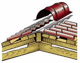
7. Skate
Ridge elements are joined with an overlap of 100 mm. The ridge is attached with 4.8 x 80 mm roofing screws to the lathing, to the top of every second wave. The flat ridge is attached with roofing screws 4.8 x 80 to the lathing or 4.8 x 35 to the sheets of metal, to the top of every second wave.
A polyurethane foam seal is placed between the ridge and the metal tile. The ends of the shaped ridge are closed with a decorative plug.
For ventilation of the under-roof space, a ridge fan is used, which is attached to the ridge with roofing screws. The joint is treated with a sealant.

8. Wall profile
In the places where the roof adjoins the wall, pipes and skylights, a wall profile is installed. The profile is applied to metal sheets and attached to the wall.

Brick rectangular pipes protruding from the roof are framed in the following way:
Step 1 - Installing the lower pipe apron
First you need to prepare the junction of the lower apron to the side surfaces of the pipe. To do this, using the elements of the apron as a template, cut lines are marked on the pipe. Then, with the help of an angle-cutting machine (grinder), a groove is made in the brick walls of the pipe. Having cleared the gate and the surface of the crate from brick dust, they begin to install the elements of the lower apron, having previously trimmed each element and bending along the slope of the roof. When installing the apron, the bent upper edge is inserted into the groove, the vertical wall is tightly pressed against the pipe surface, and in this position the element is fixed with roofing screws with a sealing gasket to the crate. First, the element is mounted to the lower edge of the pipe, then two side ones and at the end - the element to the upper edge. The overlap of the upper elements on the lower ones must be at least 150 mm. After fixing all the elements to the crate, the edge of the apron inserted into the groove is coated with silicone sealant. Attention! For better adhesion, the strobe must be rinsed with water.
Step 2 - Installation of the bottom sheet from the pipe to the cornice

At this stage, a flat (galvanized or painted) sheet is installed. The length of the sheet must correspond to the distance from the lower edge of the pipe to the cornice or the nearest valley, the width is not less than the width of the lower element of the apron (taking into account the lateral folds). One edge of the sheet is led under the lower element of the apron, and the other is led out from above, onto the cornice or valley. After fixing the flat sheet to the crate, folds are made from its sides using a hand tool.
Step 3 - Laying sheets of metal tiles along the bottom and sides of the pipe

Step 4 - Installing the wall profile
After installing the sheets of metal tiles around the pipe, they begin to finish the pipe with a wall profile. The installation procedure is the same as for the elements of the lower apron. First, a wall profile is installed to the lower edge of the pipe, with its preliminary trimming along its width, according to the figure. Fastening to the pipe is carried out using dowel-nails, and the profile is attached to the metal tile with roofing screws in the upper part of the wave.

Step 5 - Installing the wall profile from the sides of the pipe
It is necessary to process two wall profiles according to the lateral dimension of the pipe and install them on the side faces.

Step 6 - Installing the wall profile on the top edge of the pipe
Install the wall profile on the upper edge of the pipe, while trimming the vertical parts protruding beyond the pipe contour from below and bending to the side edges of the pipe, securing it with dowel-nails.

Step 7 - Installing the top sheet of metal tiles
Install the top sheet of metal tile on top of the wall profiles and sheets of metal tile installed earlier, while leaving a gap of at least 100 mm between the bottom edge of the metal tile sheet and the pipe. Place a polyurethane foam seal under the metal tile. Place a sealant in the small gap formed at the junction of the wall profile, the top and side sheets of the metal tile.

The wall profile is also used for internal fractures of the roof. On the outer fracture of the roof, a cornice element is used.

If you plan to sheathe the pipe with a profiled sheet, then after framing the pipe, a frame from a hat profile is mounted, a profiled sheet is attached to it, the corners are formed with an outer corner 50x50.
The chimney is attached to the pipe with dowel-nails before the installation of the profiled sheet.

Video of installation of metal tiles
9. Drainage system
The drainage system is used in industrial, residential and public buildings for organized drainage of water from roofs.
A drainage system with a pipe diameter of 150mm will allow to drain rainwater from 117 square meters of slope. The number of pipes on the facades of buildings will be significantly reduced. The gutter holders are mounted at a distance of no more than 0.7 m, the pipe holders - no more than 2 m from each other.
A drainage system with a pipe diameter of 100mm will allow to drain rainwater from 52 square meters of slope. The gutter holders are mounted at a distance of no more than 0.9 m from each other (design distance - 0.75 m), pipe holders - no more than 3 m from each other (for example, 3 holders are required for a 5 m long pipe, 3 m is enough two.
In case of a threat of freezing of the drainage system, it is recommended to use a heating system for gutters and pipes.
If the drainage area is less than 30 square meters, the gutters can be installed with a zero slope per one downpipe; with a larger catchment area, the slope of the gutters can be up to 2%.
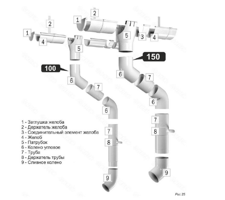
10. Installation of the drainage system:
Step 1 - Calculate the number of gutter holders.
Divide the total length of the gutter by the chosen spacing of the holders (no more than 900 mm, the recommended spacing of the holders of the gutter is 750 mm) (see Fig. 26). The resulting number of lengths +1 is the number of gutter holders.

step 2 -Marking for gutter holders.
On the bottom crate, mark the installation locations for the gutter holders with the step selected in the previous step.
step 3 -Selecting the slope of the gutter.
Select the amount of understatement of the gutter (h) based on the aesthetic perception of the gutter line. The gutter line should smoothly go down, without causing a visual sensation of a strong curvature of the edge of the slope or facing of the eaves. Recommended slope (i) the gutter is 1%, that is, from 1 cm to 1 m.The difference in the heights of the upper and lower points of the gutter (h) can be calculated as:
h = L x i
where L is the length of the gutter;
i - slope of the gutter
Step 4 - Determination of the bend locations of the gutter holders.
Number the holders from the beginning of the gutter to the gutter. Mark the place of the bend on the first holder, thus determining the initial (top) position of the chute. It is necessary to take into account when marking, so that the edge of the gutter is 2-2.5 cm lower relative to the roof slope line (see Fig. 27).

Fold the holders in ascending order of numbers and mark the folds as shown in fig. 28.

Step 5 - Fastening the gutter holders.
Aligning the bend with the edge of the lathing, attach the gutter holders to the lathing with self-drilling zinc-plated screws 4.8x22 with flat head, 3 pcs. for one holder. When using 50x50 bars as a lathing, a double bar must be installed to securely fasten the holders.
Step 6 - creating the slope
To create a slope, bend the first and last holder, pull the cord between them. Bend the rest of the holders so that they touch the cord (fig. 29).

Step 7 - Fitting the nozzle
In the groove, at a distance of 150 mm from the bottom edge, cut a hole with a diameter of 100 mm for the branch pipe. Insert the branch pipe in the place of the hole (fig. 30). Bring the leading edge of the branch pipe under the outer bend of the gutter. Bend the flange of the branch pipe to the trailing edge of the gutter and fasten with two self-tapping screws 4.2x16.
step 8 - Installing the gutter
Install the gutter plugs at the ends (Fig. 31).

Step 9 - Installing the gutter.
Insert the chute into the holders, inserting the trailing edge of the groove into the projection of the holder.
step 10 -Gutter connection.
At the junction of the gutters, install the gutter connecting element (Fig. 32).
Step 11 - Installing the angled bend.
Use the corner elbow to create a transition to the wall of the building. The length of the connecting pipe is determined locally (fig. 33).

Step 12 - Installing the pipe.
The pipe is fixed to the wall using pipe holders. The pipe is measured, if necessary, it is built up in the place of installation of the pipe holder, fixed with a lock (Fig. 34).

Step 13 - Installing the drain elbow.
A drain elbow completes the downpipe and serves to drain water from the foundation of the building. The bottom of the drain elbow should be located at a height of 300 mm from the blind area of the building (Fig. 35).
11. Snow guard and roof guard
For safe movement along the roof at the level of the eaves, starting from the second line of the sheathing, roof fences are installed.
The fence is made depending on the slope of the roof and the type of tile. Fastening is made to the lathing profile through a sheet of metal tile and a sealing rubber gasket in the place of wave deflection with self-drilling galvanized bolts 5.5x25 mm for metal lathing and 5.5x60 mm for wooden lathing. It is prohibited to fasten the roofing to one sheet of metal tile. The sections of the fence are fastened to each other with bolted connections.

To prevent large masses of snow from melting, snow holders are installed. The structure of the snow guard consists of brackets and pipes. The brackets are installed in the deflection of the wave and are attached through the metal tile and rubber gasket to the roof batten. In the places of installation for fastening the bracket, an additional lathing profile is pre-mounted at a distance of 120 mm (along the axes of the lathing profiles). Snow guards are installed above the roof railing. In the absence of a roofing fence, the snow holders are installed not lower than the third row of the crate. If the length of the slope is more than 10 meters, it is recommended to install two rows of snow guards. In areas with a large amount of snowfall, it is planned to install a bracket rod. The rod of the snow guard is attached at one end to the bracket, and at the other end to the other crate profile through a sealing gasket and a sheet of metal tile (see Fig. 38).
It is prohibited to fasten the snow retention bracket to one sheet of metal tile!


The step of installing the snow retention brackets depends on the snow area of construction, the roof structure, and the fastening element. Recommendations have been developed for calculating the step of installing the arms. The calculation is based on the use of self-tapping screws with a diameter of 4.8 mm. The immersion depth of self-tapping screws is shown in Fig. 39.

snow guards is available in the formatHtmlof this manual.
12. Accessories

Weather vane, decorative spiers, chimneys are installed as accessories on the roof. Installation of all accessories is carried out in accordance with the norms of SNiP.
Roof seals Master Flash are used for arranging exits from the roof of antennas, masts and circular ventilation pipes with a diameter of up to 330 mm (with an outer surface temperature of up to 130 °).
13. Processing of wooden structures
Wooden structures used for roofing need antiseptic and fire-retardant (fire-fighting) treatment. Processing can be carried out both before the syorki of structures (processing of individual boards and bars), and after (processing of rafters and battens). Processing is carried out by various methods (immersion in a container with a solution, application with a brush, spray application.
14. Tools

- Screwdriver with 6 mm hexagonal bit.
- Electric nibbler or nibbler.
- Manual roof shears.
- Mallets (wooden, rubber).
- Hacksaw, jigsaw, hammer (used when constructing rafters and lathing).
- Angle grinder ("grinder"), perforator, drill, gun for pressing out the sealant (used when installing the wall profile).
- Level, level, plumb line, measuring instruments and fixtures.
15. Attention!
The use of polyurethane foam as ridge or valley seals is strictly prohibited!
All products manufactured by the INSI facade and roofing plant are designed for use on pitched roofs in accordance with these installation instructions. The INSI plant is not responsible for losses or losses that may arise when using INSI products to perform functions unusual for them.