Almost every novice radio amateur has tried to assemble a radio bug. There are quite a few circuits on our website, many of which contain only one transistor, a coil and a harness - several resistors and capacitors. But even such a simple scheme will not be easy to configure correctly without special equipment. We won’t talk about the wave meter and HF frequency meter - as a rule, beginning radio amateurs have not yet acquired such complex and expensive devices, but assembling a simple HF detector is not just necessary, but absolutely necessary.
Below are the details for it.

This detector allows you to determine whether there is high-frequency radiation, that is, whether the transmitter generates any signal. Of course, it will not show the frequency, but for this you can use a regular FM radio receiver.

The design of the RF detector can be any: wall-mounted or a small plastic box in which a dial indicator and other parts will fit, and the antenna (a piece of thick wire 5-10 cm) will be brought out. Capacitors can be used of any type; deviations in part ratings are permissible within a very wide range.

RF Radiation Detector Parts:
- Resistor 1-5 kilo-ohms;
- Capacitor 0.01-0.1 microfarad;
- Capacitor 30-100 picofarads;
- Diode D9, KD503 or GD504.
- Pointer microammeter for 50-100 microamps.

The indicator itself can be anything, even if it is for high current or voltage (voltmeter), just open the case and remove the shunt inside the device, turning it into a microammeter.
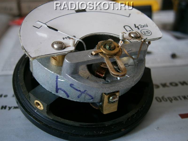
If you do not know the characteristics of the indicator, then to find out what current it is at, simply connect it to an ohmmeter first at a known current (where the marking is indicated) and remember the percentage of scale deviation.

And then connect an unknown pointer device and by the deflection of the pointer it will become clear what current it is designed for. If a 50 µA indicator gives a complete deviation, and an unknown device at the same voltage gives a half deviation, then it is 100 µA.

For clarity, I assembled a surface-mounted RF signal detector and measured the radiation from a freshly assembled FM radio microphone.

When the transmitter circuit is powered from 2V (severely shrunken crown), the detector needle deviates by 10% of the scale. And with a fresh 9V battery - almost half.

There are several ways to solve this problem in a circuit design:
The device operates on the principle of scanning radio broadcasts;
Monitoring premises for the presence of new inclusions;
Broadband electric field detection.
The best solution would be a device whose operating principle is based on broadband detection of the electric field. This principle makes it possible to detect radio transmitting devices with any type of modulation. An important factor determining the design and technological features of the device is its operating frequency range. Depending on the frequency range of the device, different requirements are imposed on its design and manufacturing technology. As frequencies increase, the required manufacturing accuracy, quality of parts processing, purity of the materials used, etc. increase. The goal of the work is to create a device operating on the principle of broadband detection of an electric field in the frequency range from 0.1 to 900 MHz; in the range of 5-300 MHz, the sensitivity of the device should be maximum. The device must have a 2-position audio alarm system.
1. Analysis of technical specifications
The device being developed, a high-frequency radiation detector, can help a person detect negative radiation.
Devices that perform these functions can also be used in the repair of various radio devices, for example, for monitoring high-frequency radiation from radios and cell phones. With their help, you can remotely monitor the radiation of switching power supplies, as well as line scans of TVs and monitors, and you can also determine the location of electronic “bugs” and other types of high-frequency electromagnetic fields.
Let's look at several specific existing devices and compare them:
High-speed search receiver SCORPIO v.3;
SIRIUS field dial indicator;
Field detector D-006.
Detailed characteristics of each device are given in Table 1.1.
Table 1.1 Characteristics of competing devices.
Let's conduct a comparative analysis of the devices. To do this, we will use the method of selection using a matrix of parameters.
We will evaluate the devices according to the parameters given in Table 1.1.
We create a matrix of parameters:

The parameters in the matrix X must be reduced to such a form that a higher value of the parameter corresponds to a better quality of the device. Parameters that do not satisfy this condition (lower limit of the frequency range, current consumption, cost, power supply) are recalculated using the following formula:
, (1.1)Having recalculated these parameters, we obtain matrix Y:

After this, the parameters of the matrix Y are normalized using the following formula:
 , (1.2)
As a result of normalization, we obtain matrix A:

For a general analysis of the system of parameters, an evaluation function is introduced:
, (1.3)Where b j is the weighting coefficient and
. Moreover, all parameters are equivalent, so b j for all parameters will be equal to 0.2.Let's define the evaluation functions using formula 1.3 and present them in matrix form):
Based on the obtained values of the evaluation function, we can say that the device being developed is better than its competitors since it corresponds to the minimum value of the evaluation function.
Structural scheme
 |
The block diagram (Figure 2.1) consists of three blocks:
In the first block, a high-frequency signal must be received and amplified. To receive a high-frequency signal, it is advisable to use an antenna, and to amplify it, it is necessary to use a high-frequency amplifier.
The second should contain a high-frequency detector, which is triggered when a high signal level is received; a comparator for comparing two signals, as well as a low-frequency pulse generator for generating an audio signal.
The third block is designed to output the signal received from the second block to the earphone.
Functional diagram
Based on the analysis of the block diagram of the device, a functional diagram can be drawn up:
 |
3.1 High frequency amplifier (HF)
The task of the VU is to amplify the signal arriving at the antenna in the range from 1 to 1000 MHz. Since the frequency range is quite wide, we will use a wideband amplifier. There are several amplifiers of this type: single-stage, two-stage and three-stage. In our case, it is advisable to use a single-stage broadband amplifier. It has a simple design and the smallest element base, which in turn will increase the reliability of the device.
3.2 High frequency detector
The high-frequency detector must detect the signal arriving at it. If the signal level received by the detector is high enough, then it should pass it. To solve this problem, you can use a conventional semiconductor diode or a Schottky diode. A distinctive feature of the Schottky diode compared to other types of semiconductor diodes is the low level of RF noise, so we will use a Schottky diode in the circuit.
3.3 Comparator
The task of the comparator is to compare two signals. In our case, for comparison, we will feed it a signal from the antenna and a signal from the square-wave generator (section 3.4). Comparators are divided into digital and analog. We use an analog comparator (AC) in the circuit, because only analog signals are implemented in the circuit. AK, in turn, can be implemented:
on an operational amplifier integrated circuit;
on a specialized analog comparator chip.
We choose the first option. We use an operational amplifier comparator in the circuit; this is the cheapest and easiest way.
3.4 Low frequency square wave generator
Designed to create an audio signal that would respond to high frequency amplification. There are several options for the circuit design of a rectangular pulse generator:
On discrete elements;
On logical elements;
On an integrated operational amplifier chip (IC op-amp);
To generate sound we use an op-amp IC. Since the comparator (clause 3.3) is also assembled on an op-amp, it is advisable to use one microcircuit for these purposes.
3.5 Low frequency amplifier
Used to amplify low-frequency impulses supplied to headphones or audio speakers. We use the simplest single-stage amplifier. This will increase the reliability of the circuit and reduce the cost.
Electrical circuit diagram
Based on the analysis of the functional diagram, we draw up an electrical circuit diagram ( DK43.418214.001E3).
The circuit consists of five functionally related nodes:
high-frequency amplifier (assembled on transistor VT1), designed to work with a signal source up to 50 Ohms (Fig. 4.1).

Figure 4.1 Single-stage broadband amplifier circuit
a high-frequency detector or a rectifier based on a Schottky diode VD1.
a comparator (on operational amplifiers N1 as part of the microcircuit), a frequency-tunable generator of low-frequency rectangular pulses (on operational amplifiers N3, N4, N5 as part of the DA1 microcircuit and transistor VT3).
key low-frequency amplifier on transistor VT2 (Fig. 4.2).

Fig 4.2 Low frequency amplifier.
The signal is taken from the antenna (WA) and goes to a high-frequency amplifier implemented on transistor VT1. If the signal level is high, the RF radiation detector is triggered (the diode VD1 opens) made on a Schottky diode. The diode turns on a comparator in the D1 chip, which is responsible for generating low-frequency pulses while stopping the low-frequency pulse generator.
The level of the signal supplied to the comparator from the detector is regulated by trimming resistor R9, which allows you to forcibly reduce the sensitivity of the device. The response threshold of the comparator is changed by variable resistor R10, which sets the initial generation frequency of the low-frequency generator. The operation of the device is indicated by LED VD2.
CONTENT:
In recent years (even, perhaps, already a decade or two), microwave radiation has become relevant. More precisely, this is electromagnetic radiation of ultra-high frequencies (frequency, approximately, from 300...400 MHz to 300 GHz, wavelength from 1 mm to 0.5...1 m). There are currently heated debates in the media about whether this radiation is harmful or not, whether it should be feared, whether it has a harmful effect or can be ignored.
We will not go deep here and engage in evidence or refutation, because the facts of the negative impact of this radiation are well known, proven by medical scientists (for example, Soviet scientists) back in the last century - the 60s. Numerous experiments were carried out on mice and rats (we don’t remember, what about other animals). They were irradiated with centimeter, decimeter and other waves of varying intensities... On the basis of these studies, Soviet GOST standards for microwave radiation were born, which, by the way, were the most stringent in the world. It was precisely because of the harmfulness of microwave radiation identified by doctors in the USSR that microwave ovens (for mass use) were banned; and not due to the supposed lack of opportunity to organize their large-scale production.
There are science articles, monographs. Anyone can familiarize themselves with them on their own. Even in Ufa they can be found in the library named after N.K. Krupskaya (now called the Zaki-Validi Library); Well, in Moscow and other similar cities, I think, there are especially no problems with this. For those who have the desire, it’s probably easy to spend a couple of days and read books with titles like “The Influence of EMR on Living Organisms.” How these very living organisms first turned red, then feverishly rushed around the cells, and then died as a result of exposure to large doses of microwaves. How long-term doses of even seemingly small levels of microwave radiation (below the thermal threshold) led to changes in metabolism (in rats, mice), partly to infertility, etc. Therefore, debate here is apparently inappropriate. Unless, of course, you pretend that this research is “wrong”, “no one knows for sure whether it is harmful or not,” etc. – only similar, so to speak, “arguments” are usually available to those who want to challenge this.
Then the market began in the USSR (that is, in the CIS). Along with the development of mobile communications. In order to somehow justify the presence of cell towers (and Internet providers), the state had to reduce the severity of GOSTs. As a result, the maximum permissible radiation doses prescribed in GOST standards have increased. Once every 10. The level that was previously considered acceptable for airfield and radar workers (such workers previously received additional payments for harmful activities and were given a number of benefits) is now considered acceptable for the entire population.
The influence of microwave radiation on living organisms
So, what does science say about the effects of microwave radiation on the body? Let's look at just some of the results scientific research conducted in the 60s...70s of the last century. Scroll scientific works and we will not cite publications here; we will limit ourselves to only a brief overview of some of them. Apparently, a considerable amount has been defended on this topic. dissertations, both candidate and doctoral theses, but most of them scientific results is probably unknown to the general public for obvious reasons. Scientists have proven that long-term systematic exposure to electromagnetic fields on the body, especially in the microwave (3×10 9 ...3×10 10 Hz) and UHF (3×10 8 ...3×10 9 Hz) ranges, at intensities above the maximum permissible, can lead to to some functional changes in it, primarily in the nervous system. Note: in those years the following maximum permissible levels of exposure to microwave and UHF energy were established:
when irradiated throughout the working day - 10 μW/cm 2 (0.01 mW/cm 2)
with irradiation up to 2 hours per working day - 100 μW/cm2 (0.1 mW/cm2)
with irradiation 15-20 min. For a working day - 1000 µW/cm2 (1 mW/cm2) with the obligatory use of safety glasses; during the rest of the day by more than 10 μW/cm2.
These changes primarily manifest themselves in headaches, sleep disturbances, increased fatigue, irritability, etc. Microwave fields with intensities well below the thermal threshold can cause depletion of the nervous system. Functional changes caused by the biological effects of electromagnetic fields in the body can accumulate (accumulate), but are reversible if radiation is eliminated or working conditions are improved.
Particularly noted are the morphological changes that can occur in the eyes and, in severe cases, lead to cataracts (clouding of the lens). These changes were detected under the influence of radiation with different wavelengths - from 3 cm to 20 m. Changes occurred both during short-term irradiation with high, thermogenic intensity (hundreds of mW/cm 2), and during long-term, up to several years, irradiation with an intensity of several mW/cm 2, i.e. below the thermal threshold. Pulsed radiation (high intensity) turns out to be more dangerous to the eyes than continuous radiation.
Morphological changes in the blood are expressed in changes in its composition and indicate the greatest impact of centimeter and decimeter waves (i.e., exactly the same waves that are used in cellular communications, microwave ovens, Wi-Fi, etc.).
Another type of change caused by exposure to electromagnetic fields is changes in the regulatory function of the nervous system, which is expressed in a violation of:
A) Previously developed conditioned reflexes
B) The nature and intensity of physiological and biochemical processes in the body
B) Functions of various parts of the nervous system
D) Nervous regulation of the cardiovascular system
Table 1
Disorders of the cardiovascular system in people systematically exposed to electromagnetic fields of different frequencies
| Field options | Percentage of cases with this disorder in the group of people studied | |||
| Frequency range | Intensity | Arterial hypotension | Bradycardia | Slow intraventricular conduction |
| Microwave (centimeter waves) (3×10 9 …3×10 10 Hz) | <1 мВт/см 2 | 28 | 48 | 25 |
| VHF (3×10 7 …3×10 8 Hz) | Below thermal threshold | 17 | 24 | 42 |
| HF (3×10 6 …3×10 7 Hz) | Tens to hundreds of V/m | 3 | 36 | - |
| MF (3×10 5 …3×10 6 Hz) | From hundreds to 1000 V/m | 17 | 17 | - |
| In the absence of fields | 14 | 3 | 2 | |
Changes in the cardiovascular system are expressed in the form of the above-mentioned hypotension, bradycardia and slowing of intragastric conduction, as well as changes in blood composition, changes in the liver and spleen, all of which are more pronounced at higher frequencies. Table 2 presents the main types of disorders that occur under the influence of microwave radiation in a living organism.
table 2
The nature of shifts in living organisms observed in chronic experiments on animals (A.N. Berezinskaya, Z.V. Gordon, I.N. Zenina, I.A. Kitsovskaya, E.A. Lobanova, S.V. Nikogosyan, M S. Tolgskaya, P. P. Fukalova)
| Features explored | Nature of changes |
| Histamine | Increased blood levels, wave-like changes |
| Vascular tone | Hypotensive effect |
| Peripheral blood | Tendency towards leukopenia, change in white lineage (decrease in segmented neutrophils) |
| Sexual function, ovarian function | Disruption of the estrous cycle |
| Fertility | Decrease in irradiated females, tendency to post-term pregnancy, stillbirth |
| Offspring | Developmental delay, high postnatal mortality |
| Eyes | Retinal angiopathy, cataract |
The biological effects of different radio frequency wavelengths generally have the same direction. However, there are some specific biological effects for certain wavelengths.
Table 3
| Wave range | Irradiation intensity | Time of death of animals in minutes and % | |
| 50% | 100% | ||
| Mid (500 kHz) | 8000 V/m | No | |
| Short | 5000 V/m | 100 | |
| 14.88 MHz | 9000 V/m | 10 | |
| Ultra short | 5000 V/m | ||
| 69.7 MHz | 2000 V/m | 1000-120 | 130-200 |
| 155 | 700 V/m | 100-120 | 130-200 |
| 191 | 350 V/m | 100-150 | 160-200 |
| Microwave | |||
| decimeter | 100 mW/cm 2 | 60 | |
| Centimeter | |||
| 10 cm | 100 mW/cm 2 | 15 | 60 |
| 3 cm | 100 mW/cm 2 | 110 | |
| Millimeter | 100 mW/cm 2 | 180 | |
Table 4
Survival of animals when exposed to different wavelengths
| Wave range | Duration of exposure that does not cause death of animals | ||
| 100 mW/cm 2 | 40 mW/cm 2 | 10 mW/cm 2 | |
| decimeter | 30 min | >120 min | >5 hours |
| 10 cm | 5 minutes | 30 min | >5 hours |
| 3 cm | 80 min | >180 min | >5 hours |
| Millimeter | 120 min | >180 min | >5 hours |
Note: 1 mW/cm2 = 1000 µW/cm2
Table 5
Animal lifespan
| Irradiation intensity, mW/cm 2 | Minimum lethal exposure, min | Dose, mW/cm 2 /h |
| 150 | 35 | 87 |
| 97 | 45 | 73 |
| 78 | 56 | 73 |
| 57 | 80 | 76 |
| 45 | 91 | 68 |
Scientific research were carried out by scientists on 493 adult male animals: 213 white rats weighing 150-160 g and 280 white mice weighing 18-22 g, which in different groups were exposed to 3-, 10-centimeter and decimeter waves with an intensity of 10 mW/cm 2. The animals were exposed to daily irradiation for 6...8 months. The duration of each irradiation session was 60 minutes. Table 6 shows data on weight gain in irradiated and control animals.
Under the influence of irradiation, certain histological changes occur in the organs and tissues of animals. Histological studies show degenerative changes in parenchymal organs and the nervous system, which are always combined with proliferative changes. At the same time, animals almost always remain relatively healthy, giving certain indicators of weight gain.
It is interesting that low doses of radiation (5-15 min) are stimulating in nature: they cause a slightly greater weight gain in animals in the experimental group compared to the control group. Apparently, this is the influence of a compensatory reaction of the body. Here, in our opinion, we can draw a (very rough) analogy with swimming in ice water: if you swim in ice water sometimes for a short time, it can help improve the health of the body; whereas CONSTANT stay in it, of course, will lead to its death (unless it is the organism of a seal, walrus, etc.). True, there is one BUT. The fact is that, after all, water is a natural, NATURAL environment for living organisms, in particular for humans (like air, for example). While microwave waves are practically absent in nature (if you do not take into account any distant ones, with the exception of the sun (the level of microwave radiation from which is very, very low), located in other galaxies, various kinds of quasars and some other cosmic objects that are sources Microwave Of course, many living organisms also emit microwaves to one degree or another, but the intensity is so low (less than 10 -12 W/cm 2) that it can be considered absent.
Table 6
Changes in the weight of animals under the influence of microwave radiation
| Wave range (animal) | Irradiation intensity, mW/cm 2 | Beginning of changes, months | Weight gain, g (average data) | |
| Irradiated | Control (not irradiated) | |||
| Decimeter (rats) | 10 | 2 | 95 | 120 |
| 10 cm (rats) | 10 | 1,5 | 25 | 70 |
| 10 cm (mice) | 10 | 1 | 0,5 | 2,9 |
| 3 cm (higher) | 10 | 1 | 42 | 70 |
| Millimeter (rats) | 10 | 3 | 65 | 75 |
Thus, in the entire range of microwave intensity waves (up to 10 mW/cm 2 = 10,000 μW/cm 2), after 1...2 months the weight of irradiated animals lags behind the weight of control animals that were not exposed to irradiation.
Thus, based on the results of studies of the effects of high-frequency electromagnetic fields of various ranges, the degree of danger of fields of various ranges has been identified, a quantitative relationship has been established between this interaction and such field parameters as strength or power flux density, as well as the duration of exposure.
For reference: modern Russian microwave standards (SanPiN 2.2.4/2.1.8.055-96, approved by the Resolution of the State Committee for Sanitary and Epidemiological Surveillance of the Russian Federation dated May 8, 1996 No. 9) radiation (maximum permissible values of energy exposure per work shift) comply parameters given in tables 7, 8.
Table 7
Table 8
Maximum permissible levels of energy flux density in the frequency range 300 MHz - 300 GHz depending on the duration of exposure

Regardless of the duration of exposure, the intensity of exposure should not exceed the maximum value specified in Table 8 (1000 μW/cm2). It is characteristic that SanPiN, unlike the corresponding Soviet standards, does not mention the need to use safety glasses.
Table 9
Maximum permissible levels of RF EMR for the population, persons under 18 years of age, and pregnant women

In addition to television stations and radar stations operating in all-round or scanning mode;
++ - for cases of radiation from antennas operating in all-round viewing or scanning mode
Thus, the maximum permissible dose is only 10 times lower than that which, with systematic irradiation for 1 hour a day, after 1...2 months causes a slowdown in development in animals. Despite the supposed “harmlessness” of microwave radiation postulated by marketers and some authorities, as well as the supposed “harmlessness” of microwave radiation by their virtual continuation on the Internet, trolls, nevertheless, for the categories of the population listed in Table 9, the maximum intensity of microwave radiation is an order of magnitude lower than for all the rest and is 10 μW/cm 2. In the case of antennas operating in all-round viewing or scanning mode (i.e., periodically irradiating a person) - 100 μW/cm 2 . Thus, the norm, which was previously established for EVERYONE, now applies only to pregnant women and minors. And so will everyone else. Well, that's understandable. Indeed, otherwise it would be necessary to completely change the concept and technology of cellular communications, as well as the Internet.
True, people stuffed with propaganda will immediately object: why, they say, there are no other technologies for communication now; Don't go back to wired communication lines. And, if you think about it, why not return? Let's continue, however.
Characteristic is paragraph 3.10 in the cited SanPiN, which states: “If the source of RF EMR is unknown, there is no information about the range of operating frequencies and operating modes, measurements of RF EMR intensity are not carried out.”
Imagine what would happen if the criminal code had a similar provision: “if the person who committed the criminal act is unknown, and there is no information about the means by which he carried out this act, a criminal case is not opened, and no search for such a person is carried out”? It is clear that this clause legally establishes the impossibility (in case the source of microwave radiation is unknown) for citizens and other persons to apply to the Sanitary and Epidemiological Station and other bodies for the purpose of measuring the level of microwave radiation.
In fact, evidence of the presence of a radiation source is, for example, the official address of a cell tower, Internet provider, etc. If the address is unknown, as well as it is unknown WHAT exactly is the source of radiation, its measurement, in accordance with paragraph 3.10, will not be carried out. Perhaps this is why, when calling the Iota company’s helpline, its operators do not provide accurate information about the location of their towers. So that, if something happens, there is nothing to complain about.
Further, even if somehow the address of a tower or other source of microwave radiation becomes known, then again, it is necessary to find out the range of operating frequencies, as well as operating modes. All this is possible only with the use of special instruments - meters, which must pass state verification. The list of such devices is kindly given in SanPiN (see Table 10).
Table 10

The cost of such devices starts from $1000...2000. It is clear that not everyone can afford to buy such a device, and even have it checked periodically by the relevant government agency. The readings of various kinds of microwave field indicators, such as those that can be purchased, for example, in the Chip and Dip store (see below), of course, will not be taken into account. There is a lot of information about this on the Internet.
What can happen to a citizen (or the head of an organization - a legal entity) who, in the absence of data about the microwave source and frequency range, despite clause 3.10 of SanPiN, will persist and persistently convince the Sanitary and Epidemiological Station of the need to carry out measurements? Of course, they can come and measure it. Or they might tell the doctors. So that they take adequate, from their point of view, measures. By the way, a lot has been written about this on the Internet too. By the way, perhaps someone (including some of our customers) may find this useful as a means of eventually getting out of the army. But in any case, there are apparently few pleasant consequences. On the other hand, there are apparently quite a few people who have real mental problems and attribute these problems to microwave radiation, judging by some messages on the Internet. To protect against such, clause 3.10 may have been introduced into SanPiN. So everyone thinks what they think. Well, we will continue to talk about the results scientific publications.
There are, of course (in the public domain), also the results of more modern scientific research. Let's say the results of a group study Ukrainian researchers (dating back to 2010) who recorded the fact significant the influence of microwave radiation from a mobile phone and WiMAX at a flux density of more than 40 μW/cm 2 on human cells. Researchers have proven an increase in the CHG indicator, which indicates a decrease in the functional activity of cells and an increase in the likelihood of mutations due to chromatin condensation in chromosomes.
The picture below is a copy of part of the first page of one of scientific publications, which discusses the results of this study. If anyone is interested, you can find and download this publication on the Internet or contact its authors directly.

There are others Scientific research, but, we repeat, here we do not set a goal to cover them even briefly, because this article does not at all pretend to scientific publication and is rather kind scientific council, no more. By the way, if you need help with preparation scientific publication, you can contact us.
Therefore in scientific We do not intend to enter into a non-scientific discussion here. The article is intended only for those who already understand what is what in relation to microwave radiation. Forcibly (or even non-violently) convincing someone, you must agree, is at least frivolous. Then, if the overwhelming majority of citizens suddenly decide and understand how harmful what they sometimes use (eat, etc.) is... You understand what will happen then. And the state will have to tighten legislation and apply repressive measures (like those used in the USA, and in Europe too). Agree, why is this necessary? It is much easier to allow a situation where everyone thinks what they want. The notorious “pluralism” of opinions was given to the people for a reason. There would be no need for it, and everyone (or rather, excuse me, almost everyone) would speak the same language, as in distant times.
So, in our article we will not talk about the harmful effects on the human body (for such an effect is obvious), but about how measure the level of microwave radiation.
Design of a microwave radiation meter
There are two ways to go. The first, relatively simple one, is to purchase a factory-made meter. However, the cost of a good meter currently (September 2014) is at least 10...15 thousand rubles (or even more). If this is the simplest meter, like the one shown in the figure below. Link to store address:
 The indicator is, without a doubt, convenient and pleasant in appearance. But, unfortunately, the selling company does not even list the frequency ranges of microwave radiation that it is capable of measuring. In addition, the minimum level of microwave radiation that this indicator can measure is unknown (the operating instructions say that it is equal to 0. But zero is an elastic concept: is it 10 -10 μW/cm 2? Or at least 10 -2 mW/ cm 2?) In addition, subsequently, such devices tend to change their readings uncontrollably. Finally, to measure microwave radiation from 5 GHz, as a rule, a device of a different price range is needed. Of course, it will be needed when the measurement results need to be proven officially. In addition, the scale of such a meter in a given frequency range is, as a rule, proportional to the power it measures. In addition, it measures microwave frequencies not in “parrots” (like a homemade one), but, say, in μW/cm 2 .
True, there is one drawback with factory meters: not all of them have good sensitivity, since they are designed to measure levels that are considered dangerous (or harmful) modern official medicine. In addition, “inexpensive” models of meters do not make it possible to determine the direction of radiation.
If anyone wants to make a homemade meter, please, there is a very inexpensive construction kit (containing ready-made parts and blocks that just need to be soldered together) from Master Kit (more details can be found on the website http://www.masterkit.ru). However, it shows the level of microwave radiation only in two modes: “less than permissible” and “more than permissible” (in the latter case, the LED on the device body lights up). It is clear that such a primitive indication is hardly relevant.
Therefore, the second way is to make your own device, fortunately, this is not so difficult. The only thing that may be difficult is the microwave diode. This is a diode that is capable of detecting (rectifying) a signal at an ultra-high frequency. With the possible exception of Moscow and a number of other cities, you won’t be able to buy such a diode in stores like “Electronics” (you can, of course, for fun, ask the sellers if they have any idea what kind of diode this is in general... only do not confuse it with a magnetron from a microwave oven). But you can only buy it by placing an order. Moreover, not every electronics store will undertake to carry it out. So it’s best to place an order either in an online store... or go to Moscow, for example, to the Mitinsky radio market. There will definitely be no problems with this. The most inexpensive microwave diode suitable for a meter can cost from 20 rubles. (used, of course). But this is not very scary: as a rule, Soviet-made microwave diodes (type D405) are fully functional even after they are disposed of due to the expiration of their service life (including by selling them at a bargain price on the radio market). It should be noted that they used to be classified as defense products (nowadays there are more modern and functional analogues); Their characteristic feature is that after a certain number of hours of operation they begin to lose their characteristics, so it is necessary to periodically replace them. In addition, it is extremely undesirable to touch them with your hands on metal parts if a person is not grounded: the fact is that they are afraid of static electricity and the breakdown voltage in the opposite direction is only 15...30 V.
The cost of a new diode will be from 100 rubles. It’s better to buy several different modifications and experiment which one is best for your device.
So, the decision was made - to solder a homemade microwave meter. According to what scheme? Let’s say right away that there are many similar schemes on the Internet. Unfortunately, ALL of them (that we happened to see) are not suitable for the reason that they only indicate modulated changes amplitudes of the received microwave signal (sometimes called beats), rather than the amplitude itself. Or they are simply not working.

Signal plot with constant amplitude

Graph of a signal with varying amplitude
In addition, these designs are often not very simple. Therefore, it is worth trying to make the scheme proposed below. Let's say right away that it does not pretend to be economical and compact. Electronics specialists, of course, will laugh at its primitiveness and lack of development... But it has only one major advantage: it works and measures the amplitude of the microwave signal, and not just its modulated change. More precisely, it allows you to measure the relative magnitude of the voltage amplitude in the received microwave signal.
How is this relative? In other words, the device takes measurements in “parrots”; Of course, it’s difficult to talk about Volts per meter or μW/cm2 here (although an attempt is made below). But the calibration is an approximate, MINIMUM estimate of the actual radiation level. Although, knowing the minimum is not bad. If, say, this very “minimum” is 100...1000 μW/cm 2, then it makes sense to comprehend the current state of affairs. Although, we repeat, in a sense it’s easier to not think about anything at all and live like this. In fact, problems with the health and well-being of a particular person are his and, basically, only his problems. True, there are still his relatives.
The fact is that to accurately calibrate the scale of this device, you will need a calibrated generator of the appropriate frequency. Moreover, you will have to calibrate not at one frequency, but at least at several (5...10). If you don’t have a generator at hand or don’t want to engage in the labor-intensive calibration process, then as a signal against which measurements will be made, it is quite possible to use, for example, a cell phone operating in signal transmission mode (voice or data over the Internet); radio internet modem (for example, Beeline or Yota), working Wi-Fi network. Having experimented with these sources of microwave radiation, it will then be easy for you to navigate with others, for example, passing (driving) past a cell tower or being somewhere in a metal-covered (quiet horror, by the way, sometimes!!) supermarket, subway, etc. .d. Then the reasons will be revealed to you, just like a magic casket, why it was “suddenly”, “out of the blue”, loss of strength appeared, nausea began, headache ached (these are, in part, signs of microwave irradiation), etc. . However, we'll talk about this a little later.
Caution: When soldering, do not bring this device too CLOSE to a running microwave oven. Because there is a danger of ruining the microwave diode. At least take care of the device (it seems that if a person does not care about his health, then it costs CHEAPER than the device), since you spent time and effort on creating it.
So, first let's look at the electrical circuit diagram.

Structurally, the circuit consists of several blocks: a measuring head, power supplies, a microammeter block, as well as a board where the rest of the circuit is assembled.
The measuring head is a half-wave vibrator with D405 diodes attached to it (or similar in characteristics, allowing for rectification of ultra-high frequency currents), D7 diodes, and a 1000 pF capacitor. All this is mounted on a plate made of thick non-foil PCB.
A half-wave vibrator is two pieces of pipe with a diameter of 1 cm made of non-magnetic metal (for example, aluminum) 7 cm long. The minimum distance between the ends of the tubes is approximately 1 cm or even less (so that the VD7 diode fits between them). As a last resort, if there are no such tubes, you can get by with a piece of thick (from 2 mm) copper wire. The maximum distance between the ends of the tubes is 15 cm, which corresponds to half the wavelength for a frequency of 1 GHz. Note that the larger the diameter of the tubes (or wires), the less the half-wave vibrator is affected by distortions in the magnitude of the received signal depending on changes in its frequency.
The design of the half-wave vibrator can be any. It is only important that good electrical contact is maintained between the diode electrodes and the ends of the tubes. For this purpose, it is advisable to plug the ends closest to each other with non-magnetic metal plugs, drilling holes in them with diameters of 8 mm and 3 mm, respectively, to a depth of 3...5 mm. We used brass tips. But you can, for example, fill the ends of the tubes to a depth of 1 cm with tin or solder, then drill holes of the specified sizes in it.
Our device used a VD7 diode of the D405 brand. Technical characteristics, as well as the dimensions of this diode are given below (taken from the reference book “Semiconductor devices. High-frequency diodes, pulse diodes, optoelectronic devices: Directory / A.B. Gitsevich, A.A. Zaitsev, V.V. Mokryakov, etc.; Under the editorship of A.V. Golomedov.-M.: Radio and Communications, 1988.-592 pp.”


The operating frequency of this diode corresponds to a wavelength of 3.2 cm (frequency 9.4 GHz). However, it can also work at lower frequencies: at least measurements at a frequency of 400 MHz (wavelength 75 cm) showed its functionality. The upper limit frequency for this diode is approximately 10 GHz (3 cm length). Thus, a meter using this diode can measure microwave radiation with frequencies of 400 MHz ... 10 GHz, which covers the range majority currently used household devices that emit microwaves: cell phones, blue-tooth, microwave ovens, Wi-Fi, routers, modems, etc. There are, of course, phones of the new standard (20...50 GHz). However, to measure radiation at such frequencies, it is necessary, firstly, a different (higher frequency) diode, and, secondly, a different design of the measuring head (not in the form of a half-wave vibrator).
The diode is quite low-power, so large fluxes of microwave radiation cannot be measured with it, otherwise it will simply burn out. Therefore, be more careful when measuring radiation from microwave ovens, as well as other powerful sources of microwave radiation! Those who voluntarily use a microwave oven for its intended purpose, of course, do not care about their health (this is their choice). But it is at least advisable to take care of the device.
Two D7 diodes in the measuring head, connected back to back, are designed to protect the VD7 diode from breakdown by static electricity (for example, if you accidentally touch the tubes of a half-wave vibrator with an electrified hand). Of course, these diodes will not withstand a high-power static discharge; for this purpose, either more powerful diodes are needed or additional protection must be constructed. However, when taking measurements at home, on the street, at work, with neighbors and friends, this was not needed. The main thing is to use the device carefully.
The current-voltage characteristics of D7 diodes are given below

Current-voltage characteristics of D7 diodes
It can be seen that there is a small scatter of parameters from sample to sample. Thus, the current-voltage characteristics for different D7 diodes are shifted relative to each other by 0.04 V.
Thus, at a voltage not exceeding 0.5 V, both diodes will open, which will insure the VD7 diode from the action of a critical (30 V) value of reverse voltage (when exposed to a microwave wave during a non-conducting period), caused, for example, by static electricity. On the other hand, even with an input voltage of 10 mV, the current values through the D7 diodes will not exceed a few tenths of a microampere. For a more accurate conclusion, the current-voltage characteristics of the diodes were interpolated in the range 0...0.35 V. It turned out that for an input voltage of 10 mV, the current through the diode is no more than 7.4 nA. In this case, the input resistance of the meter (taking into account that the input resistance of the selected operational preamplifier exceeds 50 MOhm) will be at least 10 * 10 -3 / (2 * 7.4 * 10 -9) = 576676 Ohm = 0.57 MOhm. The degree of accuracy (defined as the value of the coefficient of determination) of the interpolating trends for the D7 diodes used was less than R 2 =0.9995, i.e. almost equal to 100%.
Thus, the measuring head is an antenna (half-wave vibrator) and an amplitude detector made on an operational preamplifier. Moreover, the vibrator is loaded with a load with high resistance, significantly exceeding its wave impedance at frequencies of 300 MHz... 3 GHz. It seems that, as follows from the theory of antennas, this is incorrect, because the power received by the antenna (vibrator) must be equal to the power that is absorbed in the load. However, this state of affairs is good when the task is to obtain maximum efficiency of the radiation receiver. Our task is to realize, if possible, the independence of the meter readings from the value of the wave impedance of the antenna (more precisely, the measuring head). And efficiency, in principle, is completely unimportant. This is exactly what is ensured if
Rin of the measuring head<< R нагрузки .
Our load, of course, is an amplifier (the input impedance of the K140UD13 microcircuit and two D7 diodes connected in parallel). That is why the first amplification stage is made on an operational amplifier, and not, say, on a bipolar transistor.
Capacitor C1 is designed to accumulate an electric charge when exposed to microwave waves during a non-conducting period (this is a common element of detecting devices).
Thus, a rectified (relatively constant) voltage is obtained at the output of the measuring head.
The power sources are two sets of two Krona batteries, each with a voltage of 9 V (so that each set provides a voltage of 18 V).
Of course, it would be possible to get by with one set of two batteries by decoupling the power supply (or even with one battery by implementing a circuit that increases the voltage), but, to be honest, there was no desire to save; the main goal was to quickly create working design. If the device is not turned on for constant operation, then during occasional measurements the need to replace batteries does not arise so often. For continuous operation, it is advisable to use a stationary power source.
The microammeter block consists of the microammeter itself and a variable resistor R9. What is needed is microammeter with scale up to 10 µA, not a milliammeter. Although, you can, of course, use microammeters with other scales, for example, up to 100 μA. If you don’t find one in a store in your city, then, again, you can order it online or go to a radio store in Moscow.

Current-voltage characteristic of a microammeter with a scale of up to 100 μA
Finally, let's look at the main block. It is a printed circuit board on which the actual DC voltage amplifier circuit obtained from the measuring head is assembled. The basis of the amplifier is a precision DC operational amplifier implemented on the K140UD13. This microcircuit is a direct current operational preamplifier of the MDM type. This operational amplifier can be said to stand apart from the vast majority of its “colleagues”. For they are intended, as a rule, to enhance variable voltage, and K140UD13 amplifies constant (or slowly changing variable). The numbering of the pins of this microcircuit is shown below:

Purpose of K140UD13 pins:
1 - general;
2 - inverting input;
3 - non-inverting input;
4 - supply voltage -Up;
5 - demodulator;
6 - exit;
7 - supply voltage +Up;
8 - generator capacity; 
The K140UD13 should be powered with voltages of +15 V and -15 V, respectively.
This operational amplifier allows you to measure currents ranging from 0.5 nA, i.e. the sensitivity is very high.
Foreign equivalent: µ A727M
It is precisely this feature that this microcircuit enhances constant, but not variable current, and makes it possible to measure the value voltage amplitude Microwave radiation (rectified by the measuring head detector) as opposed to modulated voltage amplitude changes, as do the designs that can be found on the Internet. But there are cases when it is necessary to measure the unmodulated background of microwave radiation. Thus, microwave radiation from a cell phone turned on in the mode of receiving and transmitting information, but in the absence of such transmission (for example, if there was silence during a conversation) will be much less modulated than if it was present.
At inputs 2 and 3 of the operational amplifier there are the same diodes D7, connected back to back. Their purpose is exactly the same as the diodes VD5, VD6. Why duplication?
The fact is that the measuring head is connected to the device via a flexible wire (for this purpose we used a twisted telephone wire - in the form of a spiral). So, it may happen that during the measurement process, when the measuring head is moved by the experimenter’s hand (in order to determine the direction of its maximum sensitivity), the flexible wire is subject to bending. Gradually he may break away from the device. At this point (since the wire sheath is made of electrically non-conducting material), there is a high probability of a discharge of static electricity between the flexible wire and one of the inputs of the operational amplifier, which will lead to its failure. After all, the maximum value of the input common-mode voltage of the K140UD13 circuit is only 1 V. We observed a similar case, so it was decided to make a second protection - directly inside the device body, soldering two back-to-back diodes closer to pins 2, 3 of the operational amplifier.
By the way, it is also impossible to do without this protection alone (without it in the measuring head): if the flexible wire breaks, static electricity can damage the VD7 diode. Therefore, double protection is necessary. If you do not make protection, then, the most interesting thing is that the meter elements may not completely fail, but only partially. Those. The scheme will still work there somehow. At the same time, if you continue to use the microwave meter for its intended purpose, you can get quite fantastic results. The funny thing is that in many of the schemes available on the Internet today, there is no protection at all.
Transistors VT1, VT2 contain reference voltage sources that provide +15 V and –15 V at the outputs, respectively. Of course, it was possible to get by with two microcircuits such as imported L7815, L7915 or Russian KR1158EN15 voltage stabilizers, but, we repeat, the circuit was assembled quickly. Of course, using ready-made stabilizers, the circuit would be MUCH more economical than its actual version.
Resistances R2, R4 in the reference voltage sources are designed in case the zener diodes VD1, VD2 suddenly burn out, so that the reference voltage does not exceed 16.5 V and the operational amplifier DD1 does not fail. Resistors R5, R6 also serve for this purpose. The choice of the values of these resistances was carried out experimentally, by simulating the failure of zener diodes VD1, VD2.
Parts C2, C3, R5 are selected in accordance with the typical connection diagram. Capacitors C2, C3 are necessary to set the operating mode of the operational amplifier. Resistance R5 is necessary in case of a short circuit in the load of the operational amplifier: the fact is that the minimum allowable load resistance for it is 20 kOhm.
Capacitor C4 is designed to smooth out the ripples of the amplified voltage supplied from the output of the operational amplifier (so that the microammeter needle does not twitch when measuring a rapidly changing signal). Although, this capacitor is optional. Accordingly, resistance R8 is designed to allow this capacitor to discharge in the event of the microammeter unit being disconnected from the main unit (board), for example, as a result of a break or poor contact of the connecting wires during subsequent inaccurate repairs or upgrades of the device.
Finally, the microammeter unit consists of the microammeter itself and a variable resistor that regulates the voltage supply to the microammeter. The current-voltage characteristic (for example, a microammeter with a scale of 0...100 μA is taken) is given above.
Regarding the assembly of the circuit. Since the circuit does not contain any particularly critical parts, with the exception of VD7, an operational amplifier and a microammeter, it is assembled in the usual way. Regarding the VD7 microwave diode, it should be noted that it must be connected to the measuring head VERY carefully. Firstly, it CANNOT be soldered. You just need to ensure reliable tight contact with the vibrator tubes.
Secondly, when installing it in a vibrator, it is advisable to short-circuit its electrodes, for example, with a piece of foil. And remove it only when the diode is completely installed in the holes drilled in the plugs of the vibrator tubes.
If you purchase a NEW D405 diode (or similar), it will be in a special lead capsule, like a cartridge case from a small-caliber rifle. This is done so that during transportation and storage (in the retail chain) the diode does not fail as a result of exposure to static electricity or powerful electromagnetic radiation. Therefore, when installing it in the measuring head, you should remove the diode from the capsule very carefully, minimizing contact with its electrodes. It is best to slightly remove it and press the remaining electrode in the sleeve, then immediately use foil to connect the electrode emerging from the sleeve to the sleeve body itself. I hope it is clear that first the foil should be applied to the sleeve, and THEN to the electrode. Having removed the diode from the sleeve, you should immediately connect (short-circuit) its electrodes using foil and only then install it. These precautions will help preserve it. By the way, the same applies to the operational amplifier. It is advisable to short-circuit all the electrodes before soldering it into the printed circuit board, which can be done, for example, by pressing a crumpled piece of foil between the electrodes; It is advisable to remove the foil only when the circuit on the printed circuit board is completely ready.
And further. Microwave diodes in no case it is forbidden check for breakdown with a tester, ohmmeter, etc.! Because such a “check” will most likely lead to a loss of the diode’s nominal performance characteristics. Moreover, the most interesting thing is that it may not lose its full functionality. However, microwave signal detection will be much worse (sensitivity may decrease by an order of magnitude). In your mind, of course, you should take the current-voltage characteristic of this diode to make sure it is fully operational.
For the purpose of additional precautions, it is advisable to ground yourself during the assembly of the measuring head by wearing a special grounding bracelet on your leg and arm, as recommended by GOST when assembling electronic devices.
Notes. As already mentioned, the K140UD13 circuit is preamplifier. Its amplification factor, according to the passport, is no less than 10, but in any case, not 100 or 1000. Therefore, one cannot expect a significant increase in the signal received from the microwave measuring head. That’s why, by the way, a microammeter was used. If weaker signals need to be measured, then at least one more amplification stage must be added to the circuit. Since the K140UD13 is built using MDM (modulator-demodulator) technology, its output is no longer constant, but alternating voltage. To smooth it out, a C4-R7 filter is provided. Therefore, to amplify the output voltage of a DC amplifier, you can use any other operational amplifier. So, if you remove resistance R7 from the circuit and connect the input of the next operational amplifier (for example, K140UD7) instead, you can get significant gain. A device - a microwave meter - implemented in this way can be used not only for directly measuring (dangerous) levels of microwave radiation, but also for searching for weak microwave sources in the range of 400 MHz... 10 GHz. True, in order to measure microwave radiation with frequencies above 4...5 GHz, it is necessary to use a shorter wave vibrator. It is more efficient, of course, to make a broadband directional microwave antenna of small dimensions, for example, a log-periodic one. When the desire arises, we will write about it.
A high gain will allow, for example, to detect hidden microwave devices (telephones, modems, various types of listening devices operating in real time). If there is a desire to use the meter for these purposes, it should be modified. Firstly, for such purposes, a highly directional antenna is most appropriate, for example, a horn or log-periodic (so that the direction of the microwave radiation source can be determined). Secondly, it would be advisable to take a logarithm of the amplifier's output signal. If this is not done, then if, while searching for a source of a weak signal, someone nearby calls on a cell phone, the microammeter may fail (burn out).
For reference, we present the current-voltage characteristic of the considered device (microwave meter).  The dependence was removed by applying a constant voltage in the range of 2.5...10 mV to the input of the K140UD13 operational amplifier and taking microammeter readings. Due to the lack of a voltmeter of sufficient accuracy (MASTECH T M266F load clamps were used), it was not possible to measure the input voltage with a value lower than 2...2.5 mV, so the current-voltage characteristic of the meter was not taken at lower input voltages.
It can be seen that in the range of 0...3 mV it, oddly enough, is slightly nonlinear (although this may be the result of a systematic measurement error, because these load clamps, of course, do not belong to the category of professional tools). The influence of a certain measurement error (its value is not reflected in the graph) is also noticeable, which caused the deviation of the measured points from the straight line (trend) in the linear region (3...10 mV).
Microwave radiation meter calibration
Is it possible to carry out at least an approximate calibration of this meter? The microwave energy flux density incident on the antenna is calculated as follows: ![]()
W - microwave radiation flux power, W/m 2,
E – electric field strength at the vibrator,
U in – voltage between the far ends (length) of the vibrator, V,
L eff is the effective length, depending on the geometry of the meter’s receiving antenna and the received frequency, m. We approximately take it equal to the length of the vibrator, i.e. 160 mm (0.16 m).
This formula is suitable for a lossless antenna placed over a perfectly conducting ground and delivering all received power to the load (receiver). However, as already noted, in our case the power supplied to the load is minimal (since the efficiency is very low). Consequently, the microwave radiation flux density, determined from the microammeter readings of the meter and recalculated using this formula to μW/cm 2, will be lower than the actual one. In addition, the real design of a half-wave vibrator cannot be called an ideal antenna, because the real design receives the signal worse (i.e., the efficiency of the real antenna is below 100%). Thus, using this formula we obtain a minimum estimate of the power of the microwave flow incident on the measuring head.
The function of the dependence of the meter readings on the input voltage (determined from the dependence graph, see figure):
I and =0.9023U input + 0.4135
I and – current (according to the microammeter of the meter), µA,
U in – input voltage at the amplifier input, mV
Hence
U input =(I and -0.4135)/0.9023
The calculation results were as follows (see Table 11).
Table 11
Approximate correspondence of readings on the meter scale (in microamperes) to the values of radiation power in μW/cm 2
| U input, mV (for reference) | 0,65 | 1,76 | 2,87 | 3,97 | 5,08 | 6,19 | 7,30 | 8,41 | 9,52 | 10,62 |
| Meter readings, µA | 1 | 2 | 3 | 4 | 5 | 6 | 7 | 8 | 9 | 10 |
| W, µW/cm 2 | 4,4 | 32,0 | 85,1 | 163,7 | 267,7 | 397,2 | 552,1 | 732,5 | 938,3 | 1169,6 |
Thus, a deviation of the instrument needle by even 1...2 divisions (microamperes) already indicates a dangerous level of microwave radiation. If the needle deviates to full scale (i.e. the device is off scale), then the radiation level is definitely VERY dangerous (exceeds 1000 µW/cm2). Staying where this level is present is only permissible for 15-20 minutes. By the way, in accordance with even modern sanitary standards (not to mention Soviet ones), the level of microwave radiation in a place where people are, even for a short time, should not exceed the specified (limit) value.
Results of microwave radiation measurements
Attention! The information below is provided as a matter of thought and is in no way official and/or documentary. This information is completely unproven! Based on this information, no conclusions can be drawn regarding the background of microwave radiation! In order to obtain official information, interested persons should contact the Sanitary and Epidemiological Station. It has special devices that have passed state certification and verification - microwave meters, and the readings of only such devices can be taken seriously by the relevant government bodies.
Now let’s look at perhaps the most interesting thing – the results of using this device. The measurements were made in 2010-2012. The data will be given not in μW/cm 2, but in microamperes (μA) on the meter scale.
Appliances. All of the devices listed below were enabled for data (or conversation) reception and transmission. The radiation level of a Nokia GSM cell phone when measured when the distance between it and the VD7 diode located in the measuring head is 20-30 cm is 1...3...5 µA. Note that the signal fluctuates significantly in magnitude; it is maximum in dial-up mode. The Iota Internet modem gives approximately the same level (but slightly higher) of radiation; For a Hyndai Curitel CDMA 450 phone, the radiation is 1.5...2 µA (because it has a lower operating frequency and, accordingly, higher radiation power). Outside the city, a signal of 7...8 µA was also observed. More modern phones give a slightly lower level. But, not much smaller.
By the way, when a phone operating in transmit-receive mode is brought close to the measuring head, a signal of 5 or more µA is periodically observed, sometimes reaching 10 µA. Whereas at a distance of 40...50 cm the level of the measured signal decreases significantly and amounts to no more than 0.2...0.4 µA (unless, of course, you turn on the phone to receive/transmit information somewhere in places remote from cell towers communications). Apparently, the level of microwave radiation in the near zone decreases not in proportion to the square of the distance, but faster. Therefore, the solution for those who cannot give up their cell phone is to use the so-called hands-free. Measurements have shown that no radiation is transmitted through the hands-free wire. The presence of this wire does not affect the readings of the microwave radiation meter. The results of measurements taken with a hands-free earphone near the measuring head are the same as without hands-free at all. Therefore, the common Internet arguments of various kinds of trolls ("radio engineers" and other marketers) that hands-free wires, as well as the telephone network, can transmit a microwave signal are not true and are gossip. The reason here may be that these wires are very thin (so thin that sometimes even soldering them is difficult), due to which they have a high ohmic resistance. In addition, in order to transmit a microwave radiation signal, it is necessary, firstly, to first accept, i.e. The hands-free wire should act as an antenna. However, the antenna it makes is unimportant. Because, along with its small thickness, it has a high length (exceeding several wavelengths of microwave radiation from a cell phone). In addition, such a wire is somewhat twisted during operation, which causes its considerable inductance, apparently sufficient to significantly reduce the level of the microwave signal it receives. Secondly, the signal received by such an “antenna” must still be capable of (re)radiation. Re-radiation from the hands-free wire will be even lower for the reasons just mentioned. Therefore, using hands-free protects against microwave radiation emanating from a cell phone. Compared to the radiation experienced by the head of a doomed person who is talking on a cell phone, pressing it closely to his head, its (radiation) level when using hands-free decreases 10 times or more - this is on the scale of a microwave meter. If we move to units of μW/cm 2, then the power level will decrease by approximately 100 times or more. I think this is quite significant.
Also rumored is the possibility of using telephone lines to transmit microwave radiation. Although, we note that such transmission through electrical wires is quite possible, because we observed it at one time, however, only in ONE place, near one of the electrical wires with a cross section of 2.5 mm 2, located at a height of 2.2 m from the floor, despite its significant length. Wherein periodically A small background of microwave radiation was also noted in the living rooms, as well as from one of the computer monitors (old model - vacuum-beam type) while it was turned on. Then such signals disappeared (well, after some appropriate measures). Despite its great length, the electrical wire could still act as a receiver - an emitter of radiation.
Measurements in the apartment (located 200 m from the nearest cell phone tower) of one of my acquaintances, carried out at his personal request, showed a generally funny picture. The apartment in some places turned out to be full of microwave radiation at a level of 1...4 µA. Of course, there were also places where it was completely absent. At some points in space, as if for no reason at all, there were antinodes of microwave waves. Oddly enough, one of them was located... in the area of his bed, at a height of 20...40 cm from the pillow). Apparently, this is caused by interference and the formation of standing microwave waves. Well, maybe there were other reasons, because an employee lived in the apartment. We know nothing about this, and his acquaintance, according to him, was not aware of it.
The microwave oven (we don’t remember the brand, unfortunately) gave an average level of microwave radiation of 5...6 µA at a distance of another 3(!) m from it, and the signal continued to increase vigorously when trying to get closer (I didn’t want to get closer for two reasons : there was no desire to be irradiated, and there was concern for the device). Further opportunity to irradiate was soon and very kindly provided to the owners of this microwave oven. In fact, someone has to MOVE the economy by purchasing microwave ovens too. After all, with every microwave oven purchased by a Russian citizen taxes are paid to the state budget(!), wages are paid sellers in stores, drivers (who deliver these stoves), receives their money and advertising is developing etc. And if a person has already purchased a microwave oven, then let him use it later. How else? It is illogical to acquire things only for the purpose of then quickly getting rid of them.
When traveling in the city of Ufa. If you approach microwave towers, the signal level often increases sharply, then, at a distance of 300-400 meters from the tower, it decreases (on average for the towers surveyed). For example, on the street. Bakalinskaya, when moving down towards the street. Mendeleev there is a left turn. So, over the course of 300-400 meters, while we were passing this turn, the level of microwave radiation was observed to be 7...8 µA, sometimes the device even went off scale (with resistance R7 set to maximum sensitivity). It seems that, as we understand, the tower of the Iota provider is located somewhere there. The Yota company, no matter how hard we tried to find out (orally) from the operators of its help desk, did not give us accurate information about the location of the towers. Apparently, this is a commercial, or even state secret. True, the question remains: WHY hide it? On the one hand, the vast majority don’t care at all about all this. People are used to it. Headaches and loss of strength are much easier and more effective to treat with tablets than by avoiding sources of microwave radiation. Modern medicine has already, one might say, substantiated this. On the other hand, Yota’s competitors (Internet providers, Beeline, MTS), apparently, already know very well where its towers are located, if only because they have not only microwave radiation meters, but also spectrum analyzers and radio frequency scanners. Or, as sometimes happens, somewhere there, in one of the upper apartments of nearby high-rise buildings, there is, under the guise of private residence, an ILLEGAL office of an Internet provider? There is information on the Internet that similar cases occur among Internet providers and mobile operators. In any case, such secrecy is alarming.
But there are also towers from which the decrease in signal level extends further. At the television center, for example, on Zaki-Validi Street (at a distance of about 600 m from the television center tower), a level of 6...10 µA was observed.
It’s interesting, by the way, what the situation is with fences. Metal ones, of course, reflect all radiation away from themselves. Near such fences, interesting results from a physics point of view were sometimes observed. Thus, as a result (apparently) of interference, the level of microwave radiation near the metal parts of the fence increased significantly.
Wooden barriers, for example, fences (seemingly in spite of everything), are also sometimes effective reflectors of microwave radiation. Although, in theory, they should have passed it through without much attenuation. Along them, microwave radiation, emanating, for example, from the nearest cell phone tower, seems to slide and somewhat concentrate, increasing in level. The maximum level of microwave radiation is located at a surface distance of approximately 15...50 cm (one or more wavelengths). By the way, at an altitude of 4...5 m, microwave radiation is approximately 2...3 times higher. Which is apparently caused by its much lower absorption at such heights - compared to a height of 0.5...1.5 m from the surface of the earth. Because at a height of 4...5 m there are fewer building structures, fewer tree branches (by the way, trees are an EFFECTIVE barrier that absorbs and dissipates microwaves, reducing its level; not shrubs, but, let us emphasize, precisely tall trees with thick trunks), no cars, people, etc. So think carefully before cutting down a tree, even if it shades your windows. Perhaps this is your savior from microwaves.
In supermarkets and shops in Ufa. Paradoxically, the situation is different. Somewhere the level of microwave radiation is not weak (3...4 µA constantly), but somewhere it’s almost calm. We won’t say where exactly, of course. Because for the broad mass of our readers this seems to be of no use. In fact, EVERY person in the city cannot visit ALL supermarkets and shops, right?
When traveling in the city of Chishmy (Republic of Bashkortostan). There, of course, is a true PARADISE - compared to Ufa (not to mention the villages... although...). We have discovered only a few places in Chishmy, and the radiation power around each is not as high as in Ufa. At maximum, a level of 4...5 µA was observed.
Well, in conclusion
In order not to end the article on technical features and microamps. Let's talk about life-affirming, bright and positive. Remember the poem by N.A. Nekrasov "Railway?" In the end, the poet still showed a gratifying, LIGHT side, right? So, there is one acquaintance, a very good person. Somehow we started talking to him about microwave radiation and its effect on the body. So this man gave a life-affirming, “killer” argument: “yes, that’s all nonsense; I served in the army in the signal troops. So there, by mistake of one of the repairmen, poor-quality shielding was done on one cable. As a result, in the barracks for more than , than six months, the level of microwave radiation exceeded the permissible norms by more than a hundred times. And, as you can see, nothing. I, like, am not impotent (I have two children), etc. What do I need this microwave oven and, especially, a telephone ". The tragedy is that this man is only 52 years old, and in recent years he has been walking with difficulty due to gradually developing necrosis of the hip joint, and in the future, as doctors say, it will be even worse; and the spine is clearly not in order. I’ll make it, he says, somehow until retirement, 3 years left... And then they’ll cut off his leg, insert a titanium prosthesis there and sew it back on. So there are no hopeless situations!
And then... probably, it’s all a coincidence, apparently he’s right. Indeed, in fact, for example, when a person is shot at point-blank range with a pistol and then he (in the sense of a person, not a pistol) falls, then this too can be called a coincidence, looking from the outside: it was the pistol that fired the shot, but it was a man who fell. These are completely different things. Well, the bullet has nothing to do with it at all. And really, what is there, some small, unfortunate bullet, but how can it cause the fall of a person whose mass is 10,000 times higher? Now, if it was not a person who fell, but gun- then everything would be logical and explainable.
Yes, before I forget, here is another example of such a coincidence. About 7-8 years ago (in the early 2000s), a Hyndai Curitel phone with an operating frequency of 450 MHz, CDMA standard (the provider is our Ufa Sotel) was used as an Internet modem on a computer. The speed, of course, is VERY low, but the connection was absolutely stable and trouble-free, unlike the various Beeline and Megafon modems (which we also had in service and soon, after 3-4 months, were thrown into a landfill). By the way, if anyone wants, it is quite possible to test the quality of operation of such modems. Well, then go troll on the Internet, pretending that you are talking about the quality of communication. By the way, if necessary, you can approximate. But that's not what this conversation is about.
And about the cat
Which, sensing microwave radiation (it also gives heat to the body), began to periodically warm up near this phone when it was turned on to receive/transmit data. By the way, despite the fact that she was periodically driven away from the phone, she returned to it again (which, by the way, vividly reminded us of those people who, one might say, have grown together with their cell phone and even sleep, holding it in bed next to them) . By the way, the situation resembles one goat. They say that goats, and especially goats, are smart animals. So one of them, as soon as the welders began work, constantly came and literally stared and looked at the welding with literally bug-eyed eyes... apparently trying to understand for himself a new, hitherto unknown to him, natural phenomenon. Like some people, he was probably also a technological leader, a supporter of technical innovations. Well, from my own goat point of view, of course. The welders talked to the owner (who, of course, paid zero attention), drove him away, kicked the goat - everything was useless. Every time, as they said, he will come, stand up and look (from a distance of about a few meters). And soon his eyes started to leak.
So, the phone was lying on a chair, located at a distance of 1 m from the computer (the network cable no longer allowed; now, after familiarizing ourselves with the information about the effect of microwaves on living organisms, we do not use modems at such low distances at all). So, the cat, sensing the warmth (and, it must be said that the heat, which is the action of microwaves, is perceived as “piercing”, like an enveloping warm flow - if the radiation has sufficient power, of course), with visible pleasure lay down on a chair, rubbed its head on phone, purred, lay down and belly. Then, when a way was found to take the phone away from the computer (outside), the cat began to go there and again lay down next to him when he was working. It was like that for a year and a half. In direct contact with the phone, the cat's head or stomach received radiation corresponding to 5...10 µA (on the scale of the microwave meter discussed above). The radiation dose received per week was approximately 5 hours. During this period, kittens were often born dead, sick, with “oddities” (for example, with a wound in the stomach that did not want to heal for a long time). Moreover, the cat gave birth to them with difficulty, screamed loudly during contractions, rushed around the apartment in different directions (although earlier the birth proceeded normally), as a result, the kittens lay scattered throughout the house. There were few healthy kittens. Then they stopped using this phone, and another Internet modem operating at a higher frequency was used for the Internet. And the cat somehow lost interest in microwave radiation (apparently, it turned out to be more understanding than a considerable part of human citizens). After this, kittens began to be born, seemingly without any problems. There are now much fewer dead and sick people. True... she developed one strange property. Sometimes she gives birth to kittens in different places. And she is in no hurry to go feed them if they are not in her place. Kittens can lie there for so long, meowing, until they die. But if you bring them to the cat, she, somehow with dissatisfaction, but nevertheless feeds them, as if nothing had happened. Previously, sometimes, of course, she could also leave them in different places. But at least she came to feed them, regardless of where they lay. And now he’s in no hurry.
Those. Her maternal instinct was malfunctioning; it seems like for the rest of my life. By the way, a similar failure is observed, for example, in chickens raised in an incubator. They can begin to hatch chicks, seemingly sitting on eggs. And then, for no apparent reason, simply stop doing it, forgetting about it. As a result, the embryos in the eggs are underdeveloped and die. And chickens raised in an incubator are significantly different in their activity from those hatched by a chicken: the latter are barely born - and you can barely catch them. And the incubator ones are so quiet...
So the statements that supposedly cats do not like microwave radiation are nonsense. As it turned out, they still love it, even to the detriment of themselves and THEIR offspring (here an analogy with smoking and some other habits of people suggests itself). True, this applies to radiation at 450 MHz; we do not know what about higher (more harmful) frequencies - up to 30...100 GHz. In fact, after all small doses of microwave radiation are used even in medicine. Because it has been established that they contribute (at the initial stage) to the activation of life processes in the body, they can effectively warm up organs, etc. By the way, why did the cat like the radiation from the phone? In our opinion, the point here is that any cell phone (operating in signal reception and transmission mode) emits not only its main frequency (equal to 450 MHz - in this case), but also other so-called upper harmonics. The frequencies of some of these harmonics are in the terahertz (and possibly higher) range, i.e. close to the infrared region of the spectrum. It was these infrared harmonics that apparently attracted the cat - at first, because she did not immediately feel the harm from the microwave. Yes, by the way, to be precise, in medicine, i.e. in physiotherapy, not microwave radiation is used, but infrared, with frequencies above 300 GHz, which, unlike the range of 0.5...50 GHz, can have a healing effect. True, it is better not to experiment for a long time with the low-frequency part of the infrared spectrum (up to 100...200 THz). During perestroika (more precisely, the destruction of the USSR), there were reports in the press that, for example, researchers made similar generators... and then they themselves broke them - due to the development of diseases in those who came into close contact with them. Despite the seemingly not too high power of those generators. As for radiation with frequencies above 300 THz, this is already ordinary thermal radiation, visible light, etc. It's much safer. True, only up to the ultraviolet region. Radiation of higher frequencies, on the contrary, is even more harmful and destructive for living organisms (and for humans too).
But - only for initial stage. Then everything is the other way around: the body begins to collapse. True, unlike a pistol shot (when the destruction of the body occurs instantly and is therefore immediately obvious), low-power microwave radiation acts gradually, according to the principle of “a drop hits a stone,” simultaneously introducing a functional imbalance into the body. For example, when microwave radiation of sufficient power is exposed to the lens of the eye, microdamages initially appear in it, which do not affect vision at all and are therefore invisible. Over time they become larger. But, they say, there is nothing terrible here. Let's look at the situation: after all, man is not eternal. In the meantime, these various damages will accumulate there - and then it’s time for him to retire. Well, when you’re already retired, everyone will say: look at your passport and remember HOW old you are. So, you see for yourself how logical and optimistic everything is.
These are the coincidences... And, by the way, over the past decades we have also discovered the following: every time the sun rises, for some reason it becomes light. And when it sets, on the contrary, everything plunges into darkness and for some reason night falls. Moreover, historians, astronomers, and other scientists report that similar things were observed before, many thousands of years ago... So, you see, how many different coincidences there are.
With respect to you.
Let's consider the principle of operation of the detector.
The simplest receiver, as is known, is a detector. And such microwave receivers, consisting of a receiving antenna and a diode, find their application for measuring microwave power.
The most significant disadvantage is the low sensitivity of such receivers. In order to reliably detect a change in diode current under the influence of a microwave field, a microwave amplitude on the diode of several tens of millivolts is required. This is a very low sensitivity, corresponding to detecting a 10 mW transmitter at a distance of only a few meters.
In order to dramatically increase the sensitivity of the detector without complicating the microwave head (i.e., without amplifiers, converters, etc.), a circuit of a detector microwave receiver with a modulated rear wall of the waveguide was developed.
Microwave field detector with horn antenna
At the same time, the microwave head was almost not complicated; only the modulation diode VD2 was added, and VD1 remained a detector one.
Let's consider the detection process.
The microwave signal received by the horn (or dielectric) antenna enters the waveguide. Since the back wall of the waveguide is short-circuited, a standing wave regime is established in the waveguide. Moreover, if the detector diode is located at a distance of half a wave from the rear wall, it will be at a node (i.e., minimum) of the field, and if at a distance of a quarter of a wave, then at the antinode (maximum). That is, if we electrically move the back wall of the waveguide by a quarter wave (applying a modulating voltage with a frequency of 3 kHz to VD2), then on VD1, due to its movement with a frequency of 3 kHz from the node to the antinode of the microwave field, a low-frequency signal with a frequency of 3 will be released kHz, which can be amplified and highlighted by conventional ULF.
Thus, if a rectangular modulating voltage is applied to VD2, then when the microwave field drops, a detected signal of the same frequency will be removed from VD1. This signal will be out of phase with the modulating one (which will be successfully used in the future to isolate the useful signal from interference) and have a very small amplitude.
That is, all signal processing will be carried out at low frequencies, without the scarce microwave parts. Using microwave technology, you will need to make a head according to the drawings, which does not require any adjustment.
Let's consider the working design of the microwave field detector "Radar Anti" as an example.

Waveguide and horn
The waveguide and horn are made of thin copper or tinned sheet metal. You can also use foil fiberglass, having previously polished the foil and coated it with alcohol rosin flux (so that it does not oxidize).
Particular care must be taken when handling microwave diodes. They are afraid of electrostatic electricity and during a breakdown, the sensitivity to the microwave field drops by an order of magnitude or more. When checked by a tester, an electrostatically damaged diode behaves exactly the same as a working one. Therefore, when working with microwave diodes, you must take the same precautions as when working with MOS transistors.
Schematic diagram of the electronic filling of a microwave field detector.

Electronic circuit diagram of a microwave field detector