At the request of the workers, I publish the second part of the parsing of the workspace - how to turn on the tape in AutoCAD.
The topic of the lesson is as follows: how to quickly adapt the AutoCAD workspace to your own or corporate requirements and how to open the ribbon in AutoCAD. So the point is that we are duplicating the workspace. And from the copy we are already sculpting what we need.
Go…
Let's make an arbitrary space of this kind from the standard "Draw and Annotate" workspace.
It may not be entirely familiar and convenient, but everyone, ultimately, will do for themselves, and in this example we will consider the basic principles.
What do I need to do:
1. Duplicate and rename a copy of the RP "Drawing and Annotation";
2. Install AutoCAD menu ribbon on the right;
3. Convert the presentation of the tape (make it push-button);
4. Remove unnecessary tabs;
5. Add a couple of commands to the quick access panel;
6. Display and fix palettes;
How to duplicate workspace in AutoCAD
Let's take a closer look at how to duplicate and rename the Draw and Annotate workspace. To do this, open the "User interface adaptation" window, write in the CUI command line, i.e. customization of the user interface. You can also select the "Management" - "User Interface" tab on the ribbon.
In the list of workspaces, right-click on the name "Drawing and Annotation" (these actions are shown in the article "Acquaintance with the AutoCAD interface") and select "Duplicate".

We have a duplicate, now we click on it with the RMB and select "Rename" (I called " My workspace 1»), In the same way we set it" current "(for this we select" Set as default "), so that when the program starts, we immediately get into it. Then click "Apply" in the lower right corner of this dialog box, then "OK".
We are now in the space we have created. You can check it by clicking on the gear in the lower right corner. The checkbox should be checked in front of the workspace we created.
![]()
Just in case, in the parameters of the workspace, we rearrange the radio button to the item "Automatic saving of changes".
Customizing the ribbon in AutoCAD
1. To learn how to open the tape in Autocad, right-click on the tape and select "release" and the tape turns into a palette (one of the types of storage locations for tools, blocks, hatches, etc.)
2. Right-click on the edge of the palette (as in the figure below) and select "dock to the right" - the AutoCAD tape has collapsed to the line with the name "tape".

Hover the mouse over it and click "Automatically hide from the screen" in the upper part (the triangular button below the button close the "X").

3. Now let's make a prettier representation of the AutoCAD ribbon in this one, click on the arrow without an oval and select collapse to the panel buttons.

Rearrange Tabs and Panels of the AutoCAD Ribbon
By this action I mean changing the order of the panels. To do this, press and hold the left button on the desired tab and drag it to the desired location. The same algorithm is used when moving toolbars.
Removing / adding tabs of the AutoCAD Ribbon
To completely remove the AutoCAD ribbon tab, it is not enough to simply uncheck the box from the context menu - this way we simply turn off its visibility (there is a fundamental difference here).
So, to add / remove tabs, we call the already known window for adapting the user interface(command: NPI).
Select our workspace - right-click on it and select the first item "Workspace adaptation".
Move down and click on "+". In the list that opens, open the "Tabs" sublist and in it put or uncheck the boxes opposite the tab names. I will remove, for example, the Online, Output and Sheet tabs.
After making the changes, click Apply - OK.

Customizing palettes
The most commonly used palette is by far the "property palette", therefore, it makes sense to make it always at hand, but does not take up much interface space, something like this:

The fastest way to call it is the command Ctrl + 1. By analogy with the tape, we fix it to the left. We click on its edge with RMB and from the context menu select dock to the left. Right-click on it again and select only the icons.

Welcome to AutoCAD
The main window of the system will open, which, depending on the selected interface mode (ribbon, classic, combined), will look different.
Ribbon interface

AutoCAD ribbon interface
Ribbon is included by default in AutoCAD. Its characteristic feature is the presence of the toolbar at the top of the screen instead of the Draw and Edit toolbars from the sides.
Tool tape contains the basic commands for drawing, dimensioning, designations in the drawing. To many, it resembles a toolbar from Microsoft Office programs, starting with rather controversial versions of 2007. Tabs located on the Tool Ribbon: Home, Insert, Annotations, Sheet, Parameterization, View, Control, Output, Plugins, Autodesk 360, Active Applications.In the tab home there are the main tools used when creating and editing a drawing, grouped in 9 columns: Drawing, Editing, Layers, Annotations, Block, Properties, Groups, Utilities, Clipboard.
Home tab with tools
View panel
Command line area- consists of a field where the entered commands are displayed (on a gray background) and lines for their input (on a white background).
Navigation bar- contains commands for image control. You can change the scale, zoom in, delete the drawing.
Quick access menu- here are the buttons for controlling the cursor, its coordinates. Also here you can set / disable cursor snapping, enable / disable the grid (as in AutoCAD), orthogonal drawing mode.
Classic interface
The classic interface is fundamentally different from the ribbon one. For many AutoCAD users (including beginners), it is more convenient and familiar. You can enable it as follows - on the quick access panel (in the menu), switch from the mode Drawing and annotation change to Classic AutoCAD... To complete the picture, you can briefly consider it.Menu bar- from the menu File, Edit, View, Insert, Format, Tools, Draw, Dimensions, top
Toolbar Painting- left
Toolbar Editing- on right

Classic AutoCAD interface
If you wish (and if the monitor has a large screen), you can create a combined version.
By the way, hereinafter, you can see small black triangles next to the icons of different teams. They mean that besides the one displayed on the screen, there are other similar commands - to display a list of available commands, click on the image.
On this brief acquaintance with the AutoCAD interface can be considered complete.
In the previous lesson, we got acquainted with the interface of the AutoCAD program: ""
And in this lesson, we will look at how AutoCAD customization... No matter how good the standard AutoCAD interface is, there are quite a few users who find it inconvenient. That is why the manufacturers of AutoCAD have incorporated in their program ample opportunities for changing it, allowing you to customize the interface individually for each user.
For many years I have been working in AutoCAD in a two-dimensional dimension. Therefore, all the changes in the AutoCAD interface, which I will talk about below, relate to the creation of a more convenient space for working in two-dimensional space.
Workspace modes.
For many years, the AutoCAD interface included the main menu and toolbars. See Fig. 1
Rice. 1. Classic AutoCAD
Gradually, the number of instruments grew from year to year. To conveniently and compactly place a large number of tools, manufacturers have created a new interface element called the ribbon. The ribbon consists of thematic tabs, each of which contains several toolbars. See Fig. 2

Rice. 2. Drawing and annotation
AutoCAD manufacturers realized that not everyone would like this innovation. Therefore, they left the option to go to the old interface. So, since 2009 in AutoCAD, for two-dimensional drawing, two workspace modes have appeared:
1) Mode " Drawings and annotations"(By default, starting from AutoCAD 2009)
2) Mode ""
The question arose: In which of these two modes of the workspace to work better?
I think there are quite a few supporters of both one regime and the other. Both those and others will give quite a few facts to prove their preference. But, in my opinion, there is no definite answer to this question. Because a user-friendly interface is a purely individual concept. And what is convenient for one person may not be convenient for another. In addition, both in one and in the other mode, there are ample opportunities to change it. Those. to solve certain problems, both modes can be made convenient and comfortable for the user.
Since the "Draw and Annotate" mode is set by default, the number of its supporters is growing from year to year. While the number of users preferring the "Classic AutoCAD" mode is gradually decreasing.
Supporters of the "Classic AutoCAD" mode - for the most part, these are experienced users who have been working in AutoCAD for many years. And many of them know as well as I how to customize AutoCAD for themselves.
On the contrary, there are many beginners among the people working in the "Drawing and Annotation" mode. Therefore, in this lesson we will change this particular mode.
But first, let's, all the same, consider how to switch from one mode to another.
The first method: On the quick access panel, click on the name of the current workspace, and select the required mode from the drop-down list.
See Fig. 3.
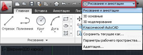
Rice. 3. Workspaces.
(but not in all versions of AutoCAD, on the quick access panel, there is such an option to switch).
Second method: In the lower right corner, click on the button for switching workspaces. And in the menu that opens, select the required mode. See Fig. 4.

Rice. 4. Workspaces.
Now let's take a look at a number of changes that, in my opinion, make the AutoCAD interface more convenient when working in two-dimensional space.
1) If we assume to work only in two-dimensional space. Then you can safely turn off the elements associated with working in 3D. Thus, we will unload the workspace:

Rice. 5. Application button
The "Settings" window will open. See Fig. 6.

Rice. 6. Window "Settings"
In it, select the "3D Modeling" tab. Uncheck all the boxes highlighted in red and click OK.
2) Disable the "Navigation Panel". Click on the button shown in Fig. 7.

Rice. 7. Close the navigation bar
The navigation that is built into the mouse is quite enough for me:
- Spin the mouse wheel forward - the drawing is approaching.
- We twist it back - it is removed.
- Click on the wheel and without releasing it, move the mouse - the drawing moves along with the workspace. We release in the right place.
- We click twice in a row on the mouse wheel - the entire drawing will be displayed in the working area.
If you want to bring back the navigation bar. See Fig. eight.

Rice. 8. Return the navigation bar.
3) Add frequently used tools to the "Quick Access Toolbar". Let's add a Layer Properties button.

Rice. 9. Adding the "Layer Property" button to the Quick Access Toolbar
Now, no matter what tab of the ribbon we are on, we can always open the "Layer Properties Manager" from the Quick Access Toolbar. See Fig. ten.

Rice. 10. Manager of properties of layers
In a similar way, add the "Layers" tool to the "Quick Access Toolbar". See Fig. eleven.

Rice. 11. Adding the "Layers" tool to the Quick Access Toolbar
and the Switch Windows tool. See Fig. 12.

Rice. 12. Adding the "Switch Windows" tool to the Quick Access Toolbar
Now we have always at hand the ability to switch layers. See Fig. 13.

Rice. 13. Switching layers.
and move from one window to another. See Fig. fourteen.

Rice. 14. Transition from one window to another.
4) Docking to the right or left of frequently used palettes. Let's make it easier to access the Properties palette.
Go to the "View" tab, click on the "Properties" button - the "Properties" palette will open. Click on the button highlighted in blue and select "Dock Left". See Fig. 15.

Rice. 15. Fixing the palette.
The Properties bar appears on the left. If you place the mouse pointer over this strip, the Properties palette appears. Moving the mouse pointer aside will hide the palette from the screen. The strip can be converted to a button. To do this, right-click on this strip and select "Icons only". See Fig. 16.

Rice. 16. Palette in the form of an icon.
At the top left, an icon will appear when you hover over which the Properties palette will appear. If you want the palette to temporarily not disappear from the screen, click on the button highlighted in red. See Fig. 17.

Rice. 17. Fixing the palette.
The palette will now be permanently on the screen. To make the palette disappear again, click on the minimize button. See Fig. eighteen.

Rice. 18. Minimize the palette.
Similarly, you can organize quick access to other palettes.
5) It happens that some of the toolbars, on any tab, collapse and they are not convenient to use. See Fig. 19. In order for them to expand, you can turn off the panels that you do not use.

Rice. 19. Disable toolbars.
To do this, place the mouse pointer on the ribbon and click the right mouse button. Next, go to "Show Panels" and uncheck those toolbars that we want to hide (in the same way, you can disable unused tabs). If the panels are still minimized, you can temporarily drag any panel into the drawing window. To do this, place the mouse cursor on the desired panel, press the left mouse button and without releasing it, drag the panel into the drawing window and release it there. Once you no longer need the panel, you can return it to the tape. We click on the button "Return the panel to the ribbon". See Fig. twenty.

Rice. 20. Return the panel to the tape.
6) Organization of quick access to the project folder. Click on the "Open" button. The "Select File" window will appear. Find the folder you would like to have quick access to (in my case, this is the "My Project" folder). We place the mouse cursor on the folder, hold down the left mouse button and, without releasing it, drag it to the "List of storages" and release it only there. See Fig. 21.
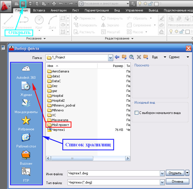
Rice. 21. Adding a folder to the list of storages.
A link to your folder will appear in the list of storages. By clicking on which you will find yourself inside the "My Project" folder. After the work with the project is finished, the link from the "List of storages" can be removed. To do this, place the mouse pointer on the desired link, press the right mouse button and select delete. See Fig. 22.

Rice. 22. Removing a folder from the list of storages.
A message will appear in which we press OK. See Fig. 23. ( The project itself will remain in the place where it lies in its integrity and safety. Only the link to it will be deleted).
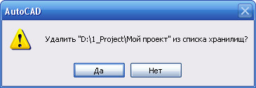
Rice. 23. Communication.
7) If you have learned the commands well and rarely use the "Context Menu". You can use the right mouse button instead of the key
This will allow you to:
- End cyclic operations by pressing the right mouse button (instead of pressing
). - Call up the last completed commands with the right mouse button without looking for them on the ribbon.
Click on the "Application button" and in the window that opens, click on the "Options" button. See Fig. 5.
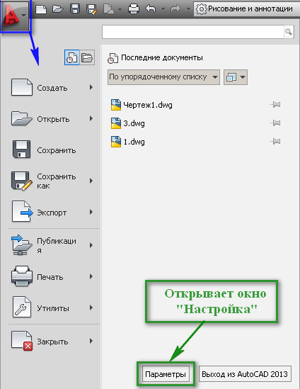
Rice. 5. Application button
The "Settings" window will open. In it, select the "Custom" tab and click on the "Right Mouse Button". The Right Mouse Button Configuration window appears. See Fig. 24.

Rice. 24. Setting the right mouse button
In this window, click on the circles highlighted in red and click on the "Accept" and "OK" buttons.
Now press the right mouse button - instead of the context menu, the "Settings" window will appear (since this is the last completed command). Just close it.
This is just a small part of how we can change AutoCAD settings.
How to create your own tabs on the ribbon. How to create your own toolbars, see the lesson: "Creating a Button for a LISP Program"
I sincerely hope that the information presented above will be useful to anyone.
Write in the comments:
What workspace mode do you work in?
What interface changes discussed in this lesson were useful to you?
If you are using something else that helps you in your work, then share your secrets.
If you want to receive news from my site. Subscribe.
A graphical editor (Fig. 1.1.) Is a program that displays graphical information on the screen and executes commands for creating, modifying, viewing a drawing and outputting it to a printer.
The main AutoCad window contains the following elements (see Fig. 1.1.):
1 - Graphic area Is a large blank area in the middle of the screen. It represents a sheet of paper, but unlike a real paper sheet, it has arbitrary dimensions and allows you to work with objects of arbitrary size. All geometric constructions and their editing are displayed in the graphics area.
2 - Crosshair: The graphic cursor is displayed in the drawing area as two intersecting lines. The movement of the crosshair can be controlled with the mouse.
3 - UCS sign: In AutoCad, all geometric objects are snapped to the global cartesian absolute system
Rice. 1.1. Graphical interface of the program
coordinates, which in this software product is called World coordinate system USC (MSC). The orientation of the axes relative to the graphic area of the AutoCad window is generally accepted: the X axis is horizontal and directed to the right, the Y axis is directed vertically upward. The angles are counted counterclockwise from the direction of the X axis. The user, if desired, can create his own user coordinate system (UCS). To create your own UCS, you must specify the origin of the UCS (the point of intersection of the axes) and the angle of rotation of the axes. After that, the point in the drawing to which the origin of the UCS is moved will have coordinates 0,0. The direction of the arrows of the sign coincides with the positive direction of the corresponding axes of the current coordinate system.
4 - Command line window (KS): all actions in AutoCad are performed using commands. A command can be set by entering its name from the keyboard, selecting from the menu, or clicking the corresponding button on the toolbar. Regardless of how you specify a command, its name appears on the command line. In it, commands are formed and all messages of the graphical editor are displayed in it.
5 - Main Menu Bar: it is a structure that allows you to quickly find the right command. The system is organized in such a way that similar commands are located in one submenu. This grouping speeds up the search for commands. In AutoCad, commands can be selected both from menus and by clicking buttons on toolbars. As a result of clicking on a button on the toolbar, the command corresponding to this button will be invoked. If you hold the mouse pointer over a button without clicking it, a comment to the button, the so-called tooltip, will be displayed next to the cursor.
6 - Standard toolbar located under the line of the Main Menu. This panel contains typical commands and some frequently encountered commands with a specific drawing.
7 - Toolbars Layers, Properties, Styles: the buttons on these panels are used to set and edit the properties of objects (line type, color and thickness, grouping of drawing elements according to their purpose) and perform other drawing processing operations.
8 - Toolbars: Almost all commands can be executed by clicking the corresponding buttons on the toolbars. Toolbars can be shown, hidden, and moved anywhere in the drawing area or docking zones. To display the toolbar, you need to right-click (PC) on any of the panels available on the screen and select the one that interests you in the context menu that opens.
9 - View cube: a tool for controlling the orientation of 3D views.
To remove it from the screen, select the command " Service → Settings → 3D Modeling → In chapter "Show viewcube" → uncheck the line "2D Wireframe vertical style -> OK.
10 - Tabs Model (Model) and Layout (Sheet): to the left of the lower scroll bar are the tabs for the model tabs and all the drawing sheets in the file. Drawings are mostly created and edited in model space, as AutoCad has the ability to create life-size drawings. This means that the user can in space Models conditionally set the size of the sheet (screen) for drawing, depending on the size of the object being created (for example, the overall dimensions of the building are 20 m by 50 m), and create a drawing in model space. This greatly facilitates the work, since the performer in the process of creating a drawing is not constrained by scaling. The arrangement of images in the drawing, its scaling, layout and preparation for printing is carried out in space Leaf.
In this tutorial we Let's start examining the workspace of the AutoCAD program. This material is related to lessons.
A workspace is understood as a set and organization of menu (ribbon) tabs and toolbars; the style and appearance of the model space; position and view of the command line; setting the status bar, etc. In general, roughly speaking, all that we see when starting the program is the AutoCAD interface.
To speak the same language, I will give you a few terms on the topic "Workspace in AutoCAD":

7 - Status bar (enable / disable drawing modes in the program).
When starting the program for the first time (starting with versions of AutoCAD 2009) by default Autocad workspace is "Draw and Annotate"(in the picture above). The menu is presented in the form of a ribbon with thematic tabs, which contain toolbars, grouped by functional belonging. This AutoCAD workspace is focused on working with 2D drawings and project documentation.
The program also provides several more pre-installed workspaces:
1. 3D basic.
2. 3D modeling.
3. Classic AutoCAD.
So let's get started!
1. Setting up and changing workspaces AutoCAD.
The workspace change button is located in the status bar in the lower right corner of the program window. To change the AutoCAD workspace, left-click (further Paintwork ) and we have a list of proposed operations .
At first, the ability to switch to a different AutoCAD workspace by clicking Paintwork by its name.
Secondly, using the option " workspace options " we call the dialog box of the same name,
![]()
in which we can configure the display of certain workspaces in the list of workspaces spaces(to do this, simply put or uncheck the boxes opposite the names of the Autocad workspaces); using buttons up down we can change the order of the spaces in the list; the separator button creates cutoffs m / d by the names of the workspaces. For the settings to take effect, press - ok.
Thirdly, consider the option " adaptation"... This option is used for global settings of the user interface, including AutoCAD workspaces. We can talk about adaptation for a very long time, so we will consider only a few settings related to today's topic.
So, after clicking on the adaptation item, the Customize User Interface dialog box, in which we see a list of workspaces.
