Reading time ≈ 3 minutes
In any private house, workshop or garage, a carpentry workbench is a very necessary item. With its help it is convenient to make or repair any things, it also combines the functions of a table and a tool shelf at the same time. It can be equipped with a bench vise, and a machine for sharpening various tools can be installed on it. If you buy a metal workbench in a store, then it will cost a considerable amount of money, but it is quite possible to make a workbench from wood with your own hands.
Necessary tools and materials
So, for the independent manufacture of a workbench in the garage, you will need the following tools:
- Hacksaw or electric jigsaw;
- Roulette;
- Square;
- Building level;
- Spanners;
- Drill;
- Screwdriver.
Materials:
- bars for supports;
- 2 sheets of plywood or OSB (one of the sheets is cut out under the shelf of the required size);
- boards for the frame;
- self-tapping screws;
- bolts;
- washers;
- nuts.
Before work, it is necessary to make a drawing of a workbench with dimensions for ease of assembly.
Step-by-step instructions for making a workbench
For the manufacture of the upper frame, it is necessary to saw off the boards based on the required size of the workbench (see photo).

Using self-tapping screws, fix 2 long and 2 short boards so that a rectangular frame is obtained. Using a tape measure, mark the distance to the middle of the frame, and fix the remaining short board perpendicularly, between two long boards, attaching it with self-tapping screws from both ends.

To make the legs of the workbench, you will need to saw off 6 equal bars. On the inside of the resulting base, fasten one leg to each corner of the frame with bolts, washers and nuts (see workbench diagram).

For the rigidity of the structure, it is necessary to put additional boards, which will also serve as the basis for the lower shelf. To do this, you need to saw off 4 boards.

With a tape measure, you need to measure an equal distance from each leg of 30 cm, at the resulting level, fix the board to the back of the structure to 3 legs, and from the front, fix the board between the extreme and middle legs, in the place where the future shelf is planned.


The remaining two boards must be fixed to the legs, at the same level as the boards for the shelves.

From one or more sheets of plywood or OSB, using a hacksaw or an electric jigsaw, we cut out the necessary segments. We fix them to the top of the workbench flush with self-tapping screws. Additionally, a sheet of hardboard can be fixed on top, because. it can be easily replaced with a new one if the old one is badly worn out. The bottom shelf is made according to the same scheme. The distance between the extreme and middle legs of the workbench is measured with a tape measure, a sheet of material is cut out according to this size and placed on the resulting base.

When attaching legs or crossbars, it is necessary to use a square to obtain an equal distance between the parts of the structure. With the help of a level, at the place of installation, you need to check whether the workbench made with your own hands is level. In the event of a slope, it must be leveled by placing wooden chips under the legs of the workbench.
1. Glue the front beam from several layers A and trim to final size (Fig. 1 and 1a). Then cut grooves in it with a width of 19 and a depth of 41 mm (Fig. 1a, photo A and V).

Brief advice! Do not glue the parts of the milling template, but fasten them only with screws. The template will again be needed to slot into the rear vise block which is wider than the cover front bar.

From a couple of pieces of thick board and 12 mm thick material, assemble a simple template for milling at an angle of 2 ° grooves, which will become holes for the bench stops.

When cutting slots in the front bar with a 12mm helical cutter and 19mm guide sleeve, remove material little by little, gradually increasing the depth.
2. Cut out the overlay V and glue it to the front beam, aligning the right ends of the parts. Carefully remove the squeezed out excess glue.
3. Using the template usually supplied with the front vise, mark and drill the holes for the rods. (photo C, fig. 1).

Position the mounting template so that the vise holes do not intersect with the bench rest holes in the A/B front bar. Mark the centers of the holes with an awl.
Note. This project uses a front and back viseLee Valley. They feature good workmanship, smooth operation and come with detailed installation instructions.
4. Now make the cover shield WITH, lower pads for the front D and rear E vice, spacer F and rear bar G. Glue the trims, back rail, spacer and front rail to the lid (Fig. 1).
5. Make the left and right tips H, I (Fig. 2). Form tongues 36 mm wide and 57 mm deep along one side of the tips and drill 12 mm holes.

Brief advice! To quickly make clean and tidy sheet piles, remove most of the material with a slotted disk and then smooth the sides and bottom with a router table.
6. Mill on the ends of the cover A-G rebate on both sides 57 mm wide and 36 mm deep (PhotoD), to form combs that are inserted into the tongues of the tips H, I.

Use the tip as a guide to cut the folds on the lid. Be careful not to hit the front trim B with the cutter.
7. Place the left tip on the comb H by pushing it to the front pad V. Right tip I align with the front edge of the shield WITH. Mark the centers of the 12mm holes (photo E). Remove the tips and use the awl to mark other centers, moving them 1.5 mm closer to the shoulders of the combs (PhotoF). Draw parallel lines, 6 mm apart on both sides of each mark left by the awl, so that the distance between the lines is 12 mm.

Use the point of a 12 mm drill to transfer the centers of the holes in the tips H, I to the ridges of the cover.

Move the centers of the holes 1.5 mm closer to the shoulders of the comb so that when driving in the dowels, the tip with the cover is pulled tighter.

With a thin round rasp, process all holes except the first. Do not go beyond the parallel lines so that the parts fit snugly.
8. Drill 12 mm holes according to the marking. Then, starting at the second hole (counting from the front edge of the lid), increase it 2mm on both sides without going beyond the parallel lines to make an oval 16mm long. Do the same with other holes, increasing the length of each next by 1.5 mm in both directions (PhotoG, rice. 2). This will allow the lid to change its width with seasonal fluctuations in humidity. In the right tip I cut 57x165mm flush with the bottom of the spacer F and the end of the bottom lining E.
9. Put on the tips H, I on the combs and secure with 12mm hardwood dowels, driving them into the holes without using glue. Saw off the protruding ends of the dowels flush with the upper and lower edges of the tips.
Brief advice! To facilitate the installation of tips, take dowels of increased length and make narrowing at their ends.
Add a vise
1. From scraps, assemble a frame that will limit the area of movement of the router when selecting a recess in the bottom plate D for front vice (photo H). Mark the recess so that it is located 70 mm from the front edge of the cover, and its middle coincides with the center of the large hole for the vise screw.

Use a 12mm ascending cutter to select a 57x305x406mm recess for the vise mechanism. Rearrange as necessary the trim supporting the router.

Peel off the back plate to slide the vise mechanism into place. Then install it again, and the operation can be considered completed.
2. Cut out the block J for the movable jaw of the front vice. Drill holes in the block, marking them with the template used earlier, positioning it so that the left end of the block is aligned with the left edge of the cover.
3. Mill along the ends of the movable jaw J shouldered fillets and attach the front vise to the cover following the directions in the instructions (photo I). Install the stock handlebar in place.
4. Cut out the block according to the indicated dimensions TO for rear clamps. Remake the milling fixture that was used before and form grooves in the block with a width of 19 and a depth of 41 mm at an angle (Fig. 3 and 3a).

5. Cut out the overlay L for rear clamps. Drill in the block TO 10mm through holes with 25mm counterbores (Fig. 3 and Per). Pressing the overlay against the block with clamps, mark the centers of the holes on it with a 10 mm drill through the holes in the block. Then drill holes with a diameter of 16 mm at the marked points. Note. Our method is slightly different from the one described in the instructions and requires the use of washers and plugs that are not included in the vise package. In doing so, we hid the bolt heads under the plugs rather than leaving them in plain sight.
6. Glue the overlay L to the block K (photoJ) and carefully remove any extruded adhesive from the bench stop holes.

Align the holes of the block K exactly with the holes of the pad L. In order not to spend a lot of time removing excess glue, apply it evenly in a thin layer.
7. Attach the assembled block K/L together with the rear vice mechanism in place, following the instructions. Close the bolt heads with plugs and install the standard handle-lever.
 Make bench stops
1. Saw according to the dimensions indicated in the "List of Materials" 17 stops M and 17 springs N. For the stops, we chose cherry wood, as it retains the required strength for a long time, does not leave dents on the parts, and its color contrasts well with the white oak wood from which the workbench cover is made. For springs, dense and elastic wood, such as maple, is suitable.
2. To give the stops the desired shape, make copies of the template, increasing them by 2 times. Then glue the springs to the stops. Check how the assembled stops fit into the holes and adjust if necessary. They should be removed and recessed without much effort and at the same time remain at the desired height. To learn more about them, read the article "Bench stops" published in this issue of the magazine.
Let's go to the base
Note. Before you start making, measure and record the dimensions of the recess on the underside of the lid. The top of the cabinet base should fit snugly into this recess. If it fails to fit, you will need to resize it to fit the recess or widen the edges of the recess for final assembly.
1. According to the dimensions indicated in the “List of Materials”, cut out the shelves O, partitions R and edge trims Q, R. Glue lining to shelves and partitions (Fig. 4). Then glue the shelves O/Q to partitions P/R and secure with additional screws.

2. Sawing plinth boards S and kings T, glue them to the O-R divider shelf assembly.
3. From 19mm cherry veneered plywood, cut out the side and back walls U, V. Glue the side walls in place first, securing with additional screws, then add the back wall, using only glue to fix it.
4. Note. Check the dimensions of the assembled body before sawing out the crossbeams, uprights and overlays and make sure that the lengths listed in the Materials List are appropriate for your project. We advise you to cut out the detailsW— GG with a slight allowance in length, and then fit them in place.

Cut out the top and bottom rails W, X, as well as racks Y (Fig. 5). Glue the top and bottom rails to the front of the base, then add the uprights.
5. Now cut out the back rails Z, AA, racks BB, mullions SS and side rails DD, EE. Glue the bottom back bar AA and mullions to the back wall V (photo K). Then glue the rear top rail and posts in place, then the side bottom rails with mullions to the side walls, and finally the top side rails and posts.

Use a couple of thick, even-edged blocks to press the SS center pieces more firmly against the back wall.
6. Mill 10 mm chamfers at the corners of the body, ending at the joints of the crossbeams with the uprights (Fig. 6).


Before connecting the plinth boards, you need to saw the bevels on the slats glued on top. After that, you can start milling fillets.
7. From the 19mm cherry boards, cut the side, front and back plinth boards FF, GG specified length with an allowance of about 3 mm in width. Then saw off a 19 x 19 mm strip from the top edge of each plinth board and mark the pieces to put them in place later. Finally, make the dovetail joints to hold the plinth boards together (Fig. 6a).Note. If instead of dovetail spikes you decide to make simple paws, cut the plinth boards of the specified width (without allowance) and do not saw off the lath from above.
8. File the miter bevels on the slats for the side plinths only, without shortening them. Glue each of them to the corresponding part from which it was sawn off. Then glue the slats without bevels to the front and back plinth boards. Bevel only the top of the front and back plinth boards so that they fit snugly into the side plinth boards. The bevel edge should be close to the marking line, and the exact mating of the parts can be achieved by fitting, removing the material little by little (PhotoL). Next, cut a 19mm fillet with a 3mm offset along the top edge of all plinth boards.
9. Glue the plinth boards to the base. You may have to use screws or nails to fasten them if you made bevels at their ends instead of dovetails.
 Add doors
1. Cut out the crossbars HH, racks II and panels JJ specified dimensions (Fig. 7).
2. Make dowels 6 mm wide and 12 mm deep centered on the inner edges of all uprights and rungs. Then form spikes 6 mm thick and 12 mm long at the ends of the crossbars.
3. Assemble the doors by gluing the posts, rails and panels together. When the glue is dry, check how the doors fit into the base opening and adjust if necessary. Then cut 5x5mm seams on the top and bottom edges of the doors on the inside, as well as 10x5mm seams on posts where there are no hinges. These rebates leave enough space between the doors and the cabinet for the installation of magnetic latches.
Attach the doors to the cabinet with the hinges and put the magnetic latches in place.
Lower the lid onto the base
1. Invite three well-built buddies to use them to lift the heavy bench top and place it on the base. There is no need to fix it - thanks to its massiveness and precise fit, it is well kept in place.
2. Once you've set up your new workbench in your workshop, immediately move on to your next project so you can enjoy your time in the workshop even more!


It is customary to call a carpentry workbench a table of a special design with a solid and durable surface that allows mounting various devices and mechanisms on it. In addition, the surface of such a table must be adapted to rigidly fix additional stationary equipment (a circular saw, for example, or a small router) used to process common materials such as wood or metal.
Before you make a carpentry workbench with your own hands, it is advisable to familiarize yourself with the basic requirements for this device, as well as with some of the most popular options.
Design requirements

The working characteristics of the table-workbench are:
- Its height, adapted to the height of the user, allows you to work in comfortable conditions without slouching, while maintaining a fairly comfortable position. For people of average height, this value can range from 70 to 90 cm.
- Dimensions of the tabletop, selected for reasons of the possibility of placing on it all the necessary tools, as well as taking into account the dimensions of the workpieces being processed.
- A set of fixtures mounted on a workbench, determined by the need to perform certain operations and providing for the presence of several stops and a clamp (screw vice).
- Adaptability "under the arm" of its owner, who may turn out to be left-handed.

The most suitable for self-manufacturing is the option of a prefabricated workbench, consisting of a frame base with a table top installed on it. The length of such a design usually does not exceed 2 meters (with a tabletop width of about 80–100 cm).
Before starting work, you should decide whether your workbench will be a stationary fixture, or whether it should be folding (collapsible).
Material selection

The most suitable material for the construction of a stationary workbench is considered to be wood, from which the supporting base with support frames, as well as the tabletop itself, are made. For the manufacture of frames, a standard planed beam with a section of 100 × 70 mm is best suited. As auxiliary jumpers that increase the rigidity of the frame base, the same bar can be used, but with a slightly smaller section (100 × 50 mm, for example).

The table top of the workbench can be assembled from well-cut and tightly fitted boards, at least 5 cm thick. In addition, a finished solid canvas (an old solid door, for example) or a blank cut from laminated chipboard with a reliable and durable finish can be used for its manufacture. coated.
When choosing a material, preference should be given to hardwoods, such as, for example, beech, oak or maple.
Construction assembly

The manufacture of a workbench begins with the assembly of a frame base, on which a table top of your choice is subsequently installed. The order of operations performed in this case is as follows:
- First of all, the supporting sidewalls are assembled, equipped in the form of two frame structures made of timber with a section of 100 × 70 mm.
- Then these frames are connected in the upper part by two longitudinal bars, which, together with the upper lintels of the frames, serve as supports for the tabletop. (Note that for reliable fastening of individual elements to each other in the design we are describing, it is best to use the classic “thorn-to-groove” connection with mandatory gluing of the docking areas).
- The lower parts of the support frames are fastened with longitudinal jumpers made of timber 100 × 50 mm, which are mounted at a level of 15–20 cm from the floor. (For their fastening, it is best to use a bolted connection recessed from the body of the bar).
- In the process of manufacturing frame supports, grooves and spikes are first prepared in blanks, after which the entire structure is assembled in one go (after applying glue to the joints).
During the assembly process, special attention must be paid to the next working moment, which determines the quality of the entire subsequent installation. When preparing the base of the workbench at each stage of the work performed, it is necessary to monitor the compliance of the dimensions of individual elements with the design data, as well as control the horizontalness of their installation using the building level.

In the case of the manufacture of countertops from planed boards, the latter must be tightly fitted to one another, so that there are no gaps in which debris usually accumulates. Its dimensions should be slightly larger (by 1.5–2 cm) than the dimensions of the supporting base formed by frames and longitudinal bars, which guarantees the convenience of placing auxiliary equipment on the table.
When assembling the tabletop, the boards are nailed or screwed with screws to the transverse bars located on its reverse plane. At the very base, special grooves for these bars should be prepared. The surface of the finished countertop is first carefully polished, and then treated with a protective solution (lining oil is usually used for these purposes). To fix it on the base, special metal corners can be additionally used.

Regarding the installation of working devices and mechanisms (vices, stops, etc.) on the workbench, the following can be said:
- It is most convenient to place a working vice on the end of the countertop, having previously prepared a small recess for fasteners at the installation site. On the reverse side of the table in the fastening area, it is necessary to provide a plywood gasket that protects the surface from damage.
- In addition, special stops should be located on the surface of the tabletop, fixing the workpiece in the working area and facilitating work with it. On a wooden tabletop, it is most convenient to mount rectangular stops (pegs), which are adjusted in height to the workpiece being processed and securely fix it.
- Sometimes stops are made by simply building up the countertop using bars of suitable thickness, fixed at its edge and closed on the back side with a limiting bar.

In the event that there is not enough space in the garage or workshop, you can make a folding workbench consisting of a tabletop that leans against the wall and a special folding frame.
This design is very easy to disassemble and when folded takes up very little space. When making it, you should pay attention to the fact that the width of the support legs of the folding workbench does not exceed half the length of the tabletop (so that they do not interfere with each other when folding).
You also need to take care that the top crossbar on the supports is located below the board with the fastening of the hinge of the reclining tabletop. The material for the manufacture of a folding workbench table can be any monolithic chipboard blank.
The supporting frames of the structure are made of bars 100 × 40 mm, the articulation of which is carried out using pre-prepared metal plates, fixed on the racks and lintels using bolts of the appropriate size.
Video
This video shows the process of building a carpentry workbench:
Photo


The carpenter's workbench is the cornerstone of the woodworker's workshop. It allows you to competently organize the workspace, increase productivity and improve the quality of work, regardless of whether you are an adherent of a manual or electromechanical tool. In this article we will tell you how to make a classic wooden workbench with your own hands.
About carpentry workbenches
The device and purpose of the workbench
A carpenter's workbench is a workbench for manual and mechanical processing of wooden products. The design and ergonomics of a classic carpentry workbench allow you to fix parts in various spatial positions and perform basic carpentry operations with maximum convenience: make wooden parts, assemble structures, cover them with finishing compounds. The traditional carpenter's table is designed to work with lumber up to 3-3.5 m long. For processing longer pieces, a carpenter's workbench is used.
The carpentry table consists of a workbench (cover) and a workbench (bearing frame). A traditional workbench is equipped with front (front) and rear (end) vices, with the help of which the workpieces are fixed in the required spatial positions.
There are holes in the table top and wooden vise jaws. They are designed to install clamps and stops of various sections and heights.

Having placed the stops in the desired configuration, a part is placed between them and pressed with a screw vise mechanism. Thus, the workpiece is securely fixed in a horizontal position. Based on the thickness of the wooden part, use a stop of the appropriate height, which will not protrude beyond the edge of the workpiece and interfere with processing.
How to choose the optimal workbench height?
The height of carpentry workbenches varies between 85-95 cm. The optimal height of the table is selected based on the growth of the master. If, standing at the workbench, the palms freely rest against its lid, then the size is chosen correctly. Behind such a workbench it will be convenient to perform all basic operations, without frequent bending and stretching, which lead to rapid fatigue.
What materials are best to make a structure?
The carpentry workbench must have sufficient strength and rigidity, since during operation it is subjected to heavy loads, both static, formed under the weight of massive workpieces, and dynamic, arising in the process of sawing, drilling, impacts, etc. Sufficient strength characteristics are provided not only by the features of fasteners, but also the type of materials used.
Coniferous wood is traditionally used for the manufacture of the base. The table top is made of durable wood: oak, beech, ash, maple, etc. The lumber used to create the workbench must be dry (moisture content of about 12%) without knots and other defects.
About making a bench cover
Experience shows that when making a carpentry workbench with your own hands, it is more expedient to purchase a ready-made glued shield, which will become a blank for the lid. The effort and time spent on cutting, jointing the edges, gluing the shield and leveling it when creating such a massive part will be incomparable with the money saved.
When performing work that increases the risk of damage to the lid: drilling, chiselling, etc., it is better to cover the working surface of the workbench with a thick plywood sheet or fiberboard cut to the shape of the lid. It is advisable to make this simple flooring immediately with a workbench.
Manufacturing and assembly of sidewalls
The design of the sidewall consists of two legs (B), tsargs and supports (A). The part is assembled on a through glued spike.

Curly cutouts of the sides and supports (detail A) are cut out on a band saw, followed by grinding the edges.
In accordance with the dimensions indicated in the diagram, the legs are marked with sockets for the spikes of the prolegs, after which they are selected with a chisel or milled.
On the outer side of the legs, a conical recess is made for the head of the coupling bolt. A recess with a diameter of 35 mm and a depth of 11 mm is made with a Forstner drill. A through hole with a diameter of 14 mm is drilled in the center.
Sawing spikes and eyelets
Spikes and lugs are made on a saw machine or by hand, guided by the basic principles for creating spiked joints. In such a critical design, the first option is preferable, since it allows you to minimize errors and inaccuracies, ensuring a flawless fit of the connection. The workpieces must have prepared smooth surfaces and correspond to the dimensions indicated in the drawing.

The halves of parts A are glued together, having previously placed an insert in the groove that will prevent displacement.

Sidewall assembly
Parts A and B are glued into a finished joint. After drying, the excess glue that has come through is carefully cleaned with a chisel. The assembled sidewall is polished.

A hole 19x38 mm is drilled in the center of the glued drawer side under the dowel (L) to fix the cover of the workbench.
Production of prolegs and underbench shelves
According to the dimensions indicated in the drawing, blanks for prolegs (detail C) are cut out in the amount of 4 pieces. Spikes are made at the ends of each part, adhering to the dimensions indicated in the photo. As in the case of the sidewall, this operation is best done on a saw machine.

The connection of the prolegs with the sidewall is made detachable on a bolt screed with a transverse nut. To do this, a recess for transverse nuts d25 mm and a depth of 32 mm is milled on the inside of the prolegs. A hole of 14x95 mm is drilled at the ends of the prolegs. At this stage, it is better to use a drilling jig, since the holes must be made strictly at an angle of 90 °.
The support strips (details D and E) are screwed with self-tapping screws with an offset of 22 mm from the upper edges of the prongs.
According to the dimensions specified in the “General Detailing” drawing, the slats of the bench shelf are cut out (detail F). Holes are drilled and countersinked at the ends of each plank. The planks are ground and sequentially mounted on the assembled frame.
Mounting the bench cover

Non-through holes d19 mm and 32 mm deep for dowels (L) are drilled on the back side of the workbench.
With a d19 mm drill, through holes are made on the lid for bench stops. Similar sockets 45 mm deep are drilled at the end of the cover. All holes are chamfered. The stops should easily enter the sockets and not play.
Advice! For all drilling operations, use a drill with a jig to ensure neat holes at a perfectly right angle. It is not difficult to make such a guide yourself, having a piece of timber at hand.

Bench vise installation
Having decided to make a workbench with your own hands, it is more expedient to buy a carpentry vice ready-made. In this case, you will get the most reliable and functional design, and, importantly, get rid of unnecessary headaches during their installation.

Manufacturers of bench vises strive to adhere to standards in the manufacture of their products. Here we will consider the installation scheme of typical structures. But it is quite possible that you will have to improvise, adapting the installation to the features of non-standard bench vise.

Vice jaws - parts H, I and J (2 pcs.) - are sawn from hardwood. After that, holes are drilled for guide rods, a lead screw, sockets for bench stops and holes for mounting screws.

The rear jaws of the front and rear vise are mounted to the workbench cover as shown in the photo.

Wooden linings (detail K) are cut to fit the vise. Through holes are drilled in the drawers for the guide rods and the lead screw.
Advice! To accurately mark the holes, use the guides themselves, pieces of masking tape and a soft pencil.

For a zealous owner, a desktop is an indispensable attribute of a garage, barn or extension to the house. Of course, a carpentry workbench can be purchased. But if this is a product of a well-known brand, then it is quite expensive. In addition, it is not known whether it will fully meet all the requests of the master. Cheap tables will not last long - definitely.
The most rational solution, if you really want to have the most convenient and versatile carpentry workbench, is to make it yourself. Having dealt with the optimal dimensions, drawings, features of the selection of materials and a number of other issues, it will become clear that there is nothing difficult in this for any man.
Selecting a workbench project
You need to start with this. Any desktop is made for some specific purposes and premises. Joiner's workbench - the name is generalized. One is needed only for woodworking on a personal plot (for example, during construction or overhaul), the other is assembled for everyday work with small details, and from different materials. Depending on the specifics of use and the place of installation, its design features, dimensions, and drawing are determined.
Option A - portable workbench (mobile). Such a desktop is most often assembled with your own hands for small rooms (an extension, a garage), with a complex layout, and its main purpose is to perform small work with small parts. The relatively low weight of the structure makes it easy to move it, if necessary, to another segment. As a rule, the maximum that such a workbench can be equipped with is a medium-sized vice and e / emery. This will allow the carpentry table to be partially used for small plumbing work.

For domestic purposes, a table according to option A is best suited for a home master. It is called mobile only conditionally, only because of its relatively low weight. If a specific place is allocated for him in a barn or garage, nothing prevents the owner from fixing his legs on the floor (fill with concrete, “fasten” with large self-tapping screws, and so on). With your own hands, whatever.

Drafting a carpentry workbench
If the workbench is assembled for domestic use, then there are recommended linear parameters (in cm) that you can focus on. But this is not an axiom, so the master himself is free to change anything, at his own discretion.
- Length - at least 180.
- Working surface width – 90±10.
- Workbench height - 80 ± 10 (taking into account the thickness of the tabletop). Deciding on this parameter, you need to focus on your own growth. It is unlikely that working with a tree will be effective and will bring satisfaction if you have to constantly slouch or, on the contrary, rise “on tiptoe”.
What to consider:
- The number and type of compartments in the cabinet table. It can be open boxes, drawers or drawers with doors, shelves. Another thing is whether the master needs them?
- To make it more convenient to work with samples of different lengths, it is worth drilling several “nests” in the tabletop to install limiters.
- To fix the workpieces, it is desirable to have a couple of clamping devices (clamps or screw vices) on the workbench. The optimal width of their "sponges" is 170 ± 5 mm.
- Desktop location. Depending on the level of illumination, the number of fixtures fixed on the workbench (and above it) is determined. But at least a couple of pieces, on the edges of the tabletop, are necessary for “spot” lighting.
If the owner is left-handed, then this should be foreseen. All standard drawings posted on the Internet are designed for craftsmen whose "working" hand is right. Therefore, you will have to place additional / equipment on the table according to the “mirror” principle.

Workbench drawing example
Selection of materials
The bar is planed. He will go to the frame (frame) of the workbench. The section is selected in accordance with the dimensions of the structure. For a large table - at least 100 x 100. If it is compact, for universal use, you can limit yourself to blanks of 100 x 70 (50). They are also perfect for various jumpers. Board. For a countertop, its minimum thickness is 50. Here you need to think about how to use the workbench more rationally. For example, to make it truly universal, one part of it can be specially adapted to perform locksmith work, that is, with metals. In this case, it is advisable to take a more massive board (for example, "sixty") and upholster a small segment of the tabletop with sheet iron. This is just one of the ideas that you can implement with your own hands when determining the design features of the workbench.
The desktop is not installed in the living quarters. And in the workshop there will definitely be differences in both temperature and humidity. So for the manufacture of a workbench, wood is recommended - hornbeam, beech, oak. The only disadvantage of this solution is the high cost of materials. You can choose a cheaper option - maple, larch. These rocks are characterized by sufficient hardness. Although for the countertop of a home-made workbench, if it is not planned to carry out any “impact” work on it, plate samples (chipboard, OSV) are sometimes taken. In principle, any good owner can easily determine what suits him best.
Too porous wood should not be used. Even its high-quality treatment with antiseptics, oils will only increase the water-repellent properties, but will not add strength to the tree.
fasteners
- Bolts. There are no particular difficulties with them. They should be of such length that a washer, grover and nut can be placed on the back side. More difficult with other types of fasteners.
- Nails. How expedient it is to use them when assembling a workbench with your own hands (and such recommendations are quite common), everyone will determine for themselves. But a number of remarks are worth making.
- Firstly, a nail, especially a large one, easily splits wood, especially if it is overdried.
- Secondly, it is unlikely that it will be possible to drive it strictly vertically, given the length of the leg and the strength of the wood from which the workbench is made.
- Thirdly, the difficulty with dismantling. For example, if it is necessary to repair the desktop with the replacement of a component. It is not always possible to pull out a tightly clogged “powerful” nail.
- Self-tapping screws. For a small workbench - the best choice. The most "problem" areas can be additionally reinforced with metal strips, corners, plates. The main thing is to correctly choose the length of the leg of the fastener. There is a rule according to which it should exceed the thickness of the fastened part by 3 times, at least. Otherwise, the strength of the connection is questionable.
Assembly instructions for a carpentry workbench
In the process of making a desktop with his own hands, the master must constantly, at every stage, control the angles and levels. The slightest distortion even in one place - and everything will have to start over.
Manufacturing of workbench parts
- This is easy to do according to the dimensions in the drawing.
- Each sample is carefully polished.
- Depending on the type of wood, an impregnating composition is selected and parts are processed to protect them from destruction by rot and wood-boring insects.
- Drying. This is worth focusing on. It is impossible to initiate this process with the help of artificial heating, otherwise the workpieces will begin to deform - bend, twist. Moisture should evaporate only naturally - in a room with room temperature and good ventilation.

Base Frame Assembly (Workbench Base)
Partially about the features of fastening has already been said - self-tapping screws + reinforcement elements. But still, the main method of fixation is a tenon-groove connection with a fit on carpentry glue. But the fasteners only add strength to the entire structure of the workbench. But this is practiced only for massive tables that are not planned to be disassembled in the future (stationary options).

Here you should consider the degree of maintainability of the workbench. If it is in a room with good conditions, then it is unlikely that the wood will quickly begin to rot. In such cases, adhesive joints are fully justified. For desktops that are located in cold sheds, unheated boxes, and even more so in the open, “landing” on glue is undesirable. Partial repairs cannot be done, and the frame will have to be reassembled.

Additional reliability of the design can be ensured by installing various jumpers - diagonal, horizontal. All this is thought out even at the stage of drawing up the drawing, although it is possible to make “refinement” during the installation process.
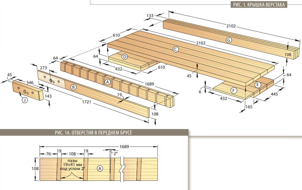
table top
This is the most loaded part of the workbench, and it is advisable to make it removable. In this case, it is easy (in case of significant damage) to replace 1 - 2 boards.
- The width of the countertop is selected so that its surface extends somewhat beyond the perimeter of the frame. Otherwise, it will be inconvenient to work on such a workbench. Yes, and fixing the removable vise will no longer work.
- The side parts of the boards are carefully polished. If you do not achieve an accurate fit of the samples, then you cannot avoid the appearance of cracks.
- The blanks are stacked face down (on a flat base) and fastened with bars. They are placed perpendicular to the center lines of the boards, and the thickness of the latter allows them to be pulled with thick self-tapping screws. In extreme cases, it is easy to drill deep chamfers at individual points.

- To make the tabletop removable, it is fixed on the frame using metal corners.
- After its manufacture, additional grinding of the front part is performed. To extend the service life, it is advisable to treat the working surface with impregnating agents (wood oil, drying oil).

Workbench equipment
At what stage and what exactly needs to be done is decided depending on the modification of the desktop and the selected drawing. For example, the same vise. They can be purchased, which are easy to attach to the edge of the workbench. People with experience in carpentry make clamping devices on their own.
In principle, a man who is “friends” with the simplest tool should not have any difficulties when assembling a carpentry workbench. The only recommendation is that before you start drawing up a drawing, you should carefully review all the photos of desktops available on the Internet.

Even if they do not have sizes, it is not difficult to determine them. But with a high degree of probability it can be argued that new, interesting ideas will appear. After all, the workbench can also be folding, which is very convenient in a small box or barn. Yes, and having familiarized yourself with the complete set of the table, the design features of various models, you can come up with something of your own, original. After all, the beauty of assembling with your own hands is in the absence of any canons. Only creativity + knowledge of the issue.