Making a home electrician project is a time consuming process that requires utmost attention to detail and appropriate professional skills. Only our company can implement a quality project with all your wishes.
Electricity supply for an apartment building
In order for the project of power supply of the village, apartment building, cottage or other site not to drag on for many years, entrust this business to us.
We will be happy to provide you with the following services:
- Unmistakable determination of the correct location of sockets, switches, lighting devices;
- Drawing up a plan for the arrangement of equipment;
- Carrying out equipment specification;
Drawing up single-line electrical diagrams for a power supply project for an apartment building or a small cottage can only be a master with solid experience.
Electrical work price-list 2016 Moscow
The price list for electrical work includes a whole range of works, including project management of any complexity on a turnkey basis. The price list for electrical work in Moscow and other cities includes:
- Installation and dismantling of wiring;
- Cable routing;
- Connection to the common house network;
- Laying of television and Internet cables;
- Installation of ventilation;
- Installation of an electrical panel;
- Connecting lighting devices;
- Installation of insulated floors, etc.
Our highly qualified craftsmen will come to you in any locality and perform work even with the most difficult tasks.
Our advantages in working on a home electrician project:
With us you will forget about the problem of finding quality materials and a responsible contractor. Our range of distinctive features includes the provision of:
- Only high quality materials
- Proven tools
- Highly qualified professional craftsmen
- Possibility of prompt departure to the point
- Established democratic pricing policy.
Our turnkey services imply a comprehensive approach to the implementation of power supply projects for a village, an apartment building, a cottage or any other settlement.
Electrical work price list 2016
As part of the implementation of an individual approach, we carefully approach the preparation of a price list for each client separately, within which you will additionally receive:
- Preparation of the necessary documentation for government agencies;
- Connecting complex household appliances;
- Electronics setup;
- Testing the work of equipment and electronics;
- Quality guarantee for several years.
We know best of all that each project is strictly individual, each project for the power supply of a village or a country house separately, an apartment building or a separate room has its own strengths and weaknesses, each design decision in the house is unique.
House power supply project
It is in our power to check, install or dismantle any power supply scheme for apartment buildings, including:
- A multi-storey building with a transformer substation;
- A multi-storey building with two cables of a transformer substation;
- A multi-storey building with two cables of a transformer substation and ATS.
We make an electrical project accurately and promptly, calculating every detail and, if necessary, discussing it with you. Therefore, you should not worry about the cost of the project of an electrician at home. After all, you will not only control our work, but you will also be able to clearly define the budget for the wiring project, beyond which we will not go.
Power supply> Concept of power supply
ELECTRIC SUPPLY OF RESIDENTIAL BUILDINGS
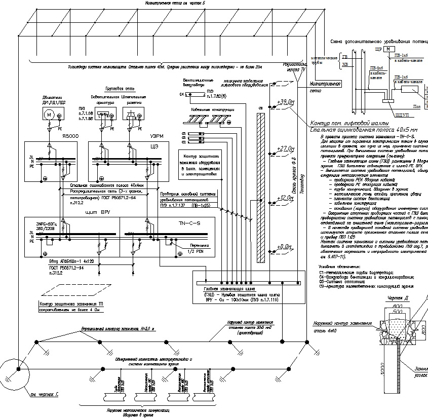
For new construction projects, in particular, the TN-C-S system is recommended. It involves grounding the metal cases of electrical equipment and connecting the sockets with three-wire wires. The RCD in this case must protect the maximum number of lines and equipment.
When combining group lines for protection with one RCD, one should take into account the possibility of their simultaneous disconnection. In addition, in multistage circuits, it is necessary to fulfill the selectivity conditions, that is, the shutdown function with a delay, in order to exclude the operation of the introductory RCD after the group one.
At modern individual construction sites (cottages, country houses, etc.), increased electrical safety measures are required. This is due to the high energy saturation, the ramification of electrical networks and the specifics of the operation of both the facilities themselves and electrical equipment. When choosing a power supply scheme such as an RCD and switchboards, you should pay attention to the need to use surge arresters (lightning arresters), which should be installed before the RCD (after the input diff-machine, in front of the meter). This is especially important to use in residential buildings powered by overhead power lines.
In individual houses, it is recommended to use RCDs with a rated current not exceeding 30 mA for group lines supplying bathrooms, showers and saunas, as well as plug sockets (inside the house, in basements, built-in and attached garages). For lines providing outdoor installation of plug sockets, the use of an RCD with a rated current not exceeding 30 mA is mandatory.
Power supply schemes for residential buildings.

Typical project of a 17-storey residential building
EOM - power electrical equipment, electrical power networks and electric lighting of an apartment building.
This section of the project deals with electrical power equipment, electrical power networks and electrical lighting of an apartment building.
The power supply of the main equipment in terms of the degree of reliability assurance belongs to category II in accordance with the PUE classification and the requirements of SP 31.110-2003 and is carried out through two cable entries from an external power supply network with a voltage of ~ 380 / 220V AC with a frequency of 50 Hz. Grounding system for ASU type TN-S-S.
The power supply of the facility is provided from the RU-0.4 kV of the designed stand-alone RTP.
The input distribution device of the ASP is powered by two mutually redundant cable lines of the APvzBbShp-1 2x (4x120) brand. The cables are laid in a trench, in the ground at a depth of 0.7m.
For the distribution of power supply to power electrical equipment, lamps of the main and emergency lighting, the project provides for electrical distribution boards SCHAV, SCHSS, PPN.
To supply power to category I electrical consumers, the project provides for the installation of an automatic transfer switch.
For electrical receivers of the I category of power supply reliability, according to SP 31.110-2003 tab. 5.1, include:
Light shielding lights;
Elevator equipment;
Emergency lighting;
CCTV;
Fire warning system;
Dispatching system equipment (ACS);
Security and communication systems;
Pumping stations;
Fire-fighting devices (back-up and smoke exhaust systems, smoke exhaust valves, fire extinguishing systems);
The uninterruptible power supply provides autonomous power supply for at least 1 hour.
Power equipment.
The power supply network of power electrical equipment is carried out with VVGngLS 3x [S] cables, in corrugated PVC pipes on the ceiling, in the preparation of the floor and in metal trays, in the wall grooves and cable channels, in accordance with the technological plan for the placement of technological and other equipment.
In the event of a fire, it is envisaged to turn off the exhaust ventilation of the air by turning off the switchboard of the B1 system.
The ventilation unit is powered by an independent line from the V1 switchboard. The smoke exhaust fans are controlled by means of control boxes of the Ya5000 type (or similar).
Passenger elevator control panel, supplied complete with equipment.
The operation of the pumps is controlled from the control stations that are part of the pumping units supplied complete with the equipment.
The operation of light-shielding lights (ZOM) is controlled from the control panel, which are part of the installation, supplied complete with the equipment.
Electricity of the net
The power supply network for household and technological sockets is carried out with a VVGngLS 3x2.5 cable in PVC pipes with a diameter of 20 mm.
The sockets are installed on the wall in accordance with the height marks indicated on the plan.
Blue - neutral working conductor (N);
Green - yellow - neutral protective conductor (PE);
Black or other colors - phase conductor.
In accordance with clause 7.1.49 of the PUE, for a three-wire network, install plug sockets for a current of at least 10A with a protective contact, which must have a protective device that automatically closes the sockets when the plug is removed.
Daisy chain connection of the PE conductor is not allowed (PUE 1.7.144).
The PVC pipe must have a fire safety certificate (NPB 246-97).
Electrical equipment and materials used during installation must have a certificate of compliance with Russian standards.
Electric lighting
Electric lighting of premises is carried out in accordance with SP 52.13330.2011 "Natural and artificial lighting".
Group networks of working and evacuation lighting are made with VVGng-LS 3x1.5 cable, in PVC pipes on the ceiling.
Group emergency lighting networks are made with VVGng-FRLS 3x1.5 cable, in PVC pipes on the ceiling.
The project provides for a combined lighting system and the following types of artificial lighting: working, emergency (backup and evacuation) and repair. Working and emergency lighting network voltage - 220V, repair - 36V.
To accommodate the automation and protection of electric lighting, the project provides for the installation of a ShchO lighting switchboard and emergency lighting ShchAO.
Luminaires with LED and fluorescent lamps are used in the project.
The choice of luminaires was made in accordance with the purpose of the room and the characteristics of the environment, as well as in accordance with the terms of reference.
In public areas, emergency lighting fixtures are used for emergency lighting at night.
Switches and switches are installed on the wall from the side of the door handle at a height of 1000 mm from the floor.
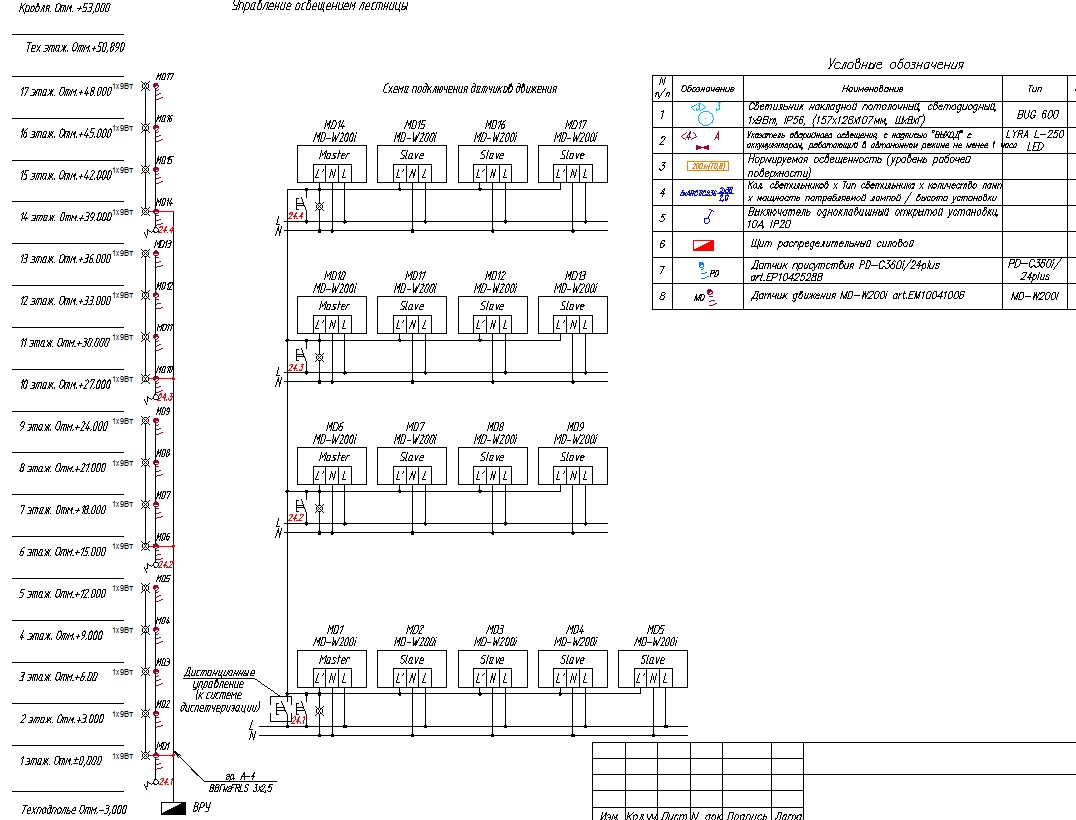
The project provides for manual (local) lighting control, as well as remote control from the control room. To save electrical energy, automatic lighting control is provided using motion sensors (on the escape stairs) and presence sensors (lift hall and corridor).
The project provides for the installation of a system of obstruction lights (ZOM) on the roof.
Electric shock protection
To ensure the safety of people, the working documentation provides for all types of protection required by GOST R 50571.1-93 (IEC 364-1-72, IEC 364-2-70) "Electrical installations of buildings. Basic position". Protection against direct contact is ensured by the use of double-insulated wires and cables, electrical equipment, devices and lamps with a degree of protection of at least IP20.
All metal parts of electrical equipment that are normally not energized, metal structures for the installation of electrical equipment, metal pipes for electrical wiring are subject to protective grounding in accordance with the requirements of the PUE for networks with a dead-grounded neutral point 1.7.76 PUE ed. 7.
Protection against indirect contact is performed by automatic shutdown of the damaged network section by overcurrent protection devices and by implementing a potential equalization system. A residual current device (RCD) is used to protect against low fault currents, reduce the insulation level, as well as in the event of a break in the neutral protective conductor.
Electricity metering
Commercial metering of electricity is carried out at the border of the balance sheet in the ASU.
Use three-phase electronic meters, transformer-type Mercury230 ART02-CN 5-10A, which have a telemetric output for connection to ASKUE (the type of meter should be coordinated additionally with the services) as sensors for input control of electricity.
Lightning protection system
Object classification.
Object type - Multi-apartment residential building. Height 45 m. The design adopted category III lightning protection in accordance with SO 153-34.21.122-2003.
III level of protection against direct lightning strikes (PUM) - reliability of protection against PUM 0.90. The complex of projected means includes a device for protection against direct lightning strikes (external lightning protection system - MZS) and protection devices against secondary effects of lightning (internal MZS).
External lightning protection system
Use a metal mesh made of galvanized steel wire with a diameter of 8 mm (section 50 sq. Mm) as a lightning rod. Use fittings Art. f8 GOST 5781-82. Lay the mesh on a layer of insulation, over the roof screed. Cell spacing is not more than 15x15m. Connect the mesh nodes by welding. All metal structures located on the roof (ventilation devices, fire escapes, gutters, fencing, etc.) must be connected to the mesh by welding rods Ø 8 mm; length of welded seams - at least 60 mm. All protruding non-metallic structures are also protected with a wire laid on top along the perimeter of the structure and connected to an air termination mesh.
Down conductors are located along the perimeter of the protected object. Use galvanized steel strip 25x4 as down conductors. The location of the down conductors is shown on the plans. Down conductors will be connected by horizontal belts at elevations +12.00, +27.00 and + 39.00 m.
Reinforcement of a reinforced concrete foundation, connected by welding with a steel strip 50x4 in accordance with GOST 103-76, was adopted as a ground electrode by the project. The lightning protection grounding strip is laid around the task, at a depth of at least 0.7 m from the earth's surface. The soil is loam with a resistivity of 100 Ohm * m. The length of the horizontal earthing switch D = 115.6 m.
Estimated resistance to current spreading no more than R = 4.0 Ohm;
System material - Steel.
All connections are welded. Provide anti-corrosion coating for all exposed elements of the lightning protection system. To protect the ground loop from soil corrosion, cover its elements with MBR-65 bitumen mastic (GOST 15836-79), no more than 0.5 mm thick.
Connect the lightning protection earthing switch to the GZSH at the ASP.
Protection against secondary effects of lightning.
To protect against the drift of high potential through external metal communications, they must be connected to the ground electrode of the lightning protection system at the entrance of communications into the building. Make the connection with a steel strip with a section of 40x4 (GOST 103-76).
To protect people in elevator shafts from step voltages and touch voltages that may arise on the floor and lifting equipment, lay a circuit in the shafts around the said equipment. The contour is made of 40x4 steel strip. Perform the contour on the horizon +12.00 +27.00 and + 39.00m. To equalize the potentials, connect the metal parts of the frame of the lifting mechanisms to the contours. Connect the elevator protection circuit with the GZSH.
All connections are welded.
Provide anti-corrosion coating for all elements of the lightning protection system. To protect the system elements from soil corrosion, cover its elements with MBR-65 bitumen mastic (GOST 15836-79).
Note on the installation of earthing pipelines:
The metal pipelines should be grounded at the input from the side of the building, in places accessible for maintenance. Connect all external metal pipelines to an artificial grounding conductor of the external lightning protection system. Use a 40x4 steel strip for the connection.
For cast-iron sewage pipes, use a clamp outlet made of 08X13 steel. Install the clamps on a bare metal. shine the pipe with subsequent processing of the junction with technical petroleum jelly.
Mount the attachment points in accordance with the instructions of U-ET-06-89.
The transition resistance of the connection is not more than 0.03 Ohm for each contact.
Agree with Mosvodokanal the grounding of the water supply system in accordance with UDC 696.6,066356 clause 542.2.1, clause 542.2.5.
Grounding and potential equalization system.
Use the lightning protection ground loop as a re-grounding conductor.
Use the PE VRU bus as the GZSH bus.
Connect the external ground loop to the GZSH. For connection, use steel strip St.50x4.
Weld the connection. For strip steel conductors, weld length 100 mm, height 4 mm. Make connections with pipes in accordance with the nodes shown in the drawing or in accordance with the requirements of the standard album of the 5.407-11 series ("Grounding and grounding of electrical installations.) Paint the places of external connections and external steel connecting conductors with MBR-65 bitumen mastic.
Perform potential equalization according to the diagram (see sheets 41 and 40).
The equipotential bonding conductors, which are not part of the cable, must be laid openly, with fastening to the building structure with metal brackets. Determine the distance between the fasteners during installation. Lay through the walls in sleeves with a diameter ensuring free passage of the conductor. Hidden laying in fire-hazardous, hot, damp rooms is allowed.
List of working drawings of the main set of the EOM brand:
- 1. General data
- 2. Scheme electrical principal single-line input-distribution device VRU
- 3. List of electrical consumers and calculation of electrical loads
- 4. Typical nodes
- 5. Schematic electrical schematic single-line switchboard ShchSS1
- 6. Electrical schematic diagram of a single-line switchboard of the DF switchboard
- 7. Schematic electrical schematic single-line switchboard of the distribution board SCHSS3
- 8. Schematic electrical schematic single-line switchboard of the distribution board SCHSS2 and Ya5111
- 9. Schematic electrical diagram of a single-line switchboard of a distribution floor switchboard
- 10. Schematic electrical schematic single-line switchboard ShchM
- 11. Scheme for connecting active electricity meters to current transformers
- 12. Electrical schematic diagram of a single-line switchboard of a distribution storey ATS
- 13. Installation diagram. General view of AVR
- 14. Installation diagram. General view of the UERM evacuation ladder
- 15. Electrical control circuit for the lighting of the elevator hall and corridors
- 16. Group lighting network of those. underground
- 17. Group lighting network of the 1st floor
- 18. Group lighting network 2 ... 17 floors
- 19. Power electrical equipment and group lighting network of the technical floor
- 21. Power electrical equipment of those. underground
- 22. Power electrical equipment of the 1st floor
- 23. Power electrical equipment 2 ... 17 floors
- 24. Grounding and lightning protection of the building
- 26. Diagram of the main potential equalization system of the building
- 27. Plan for entering cables from the trench into the building of 0.4 kV networks (section)
- 28. Plan for entering cables from the trench into the building of 0.4 kV networks
Electrical schematic diagram of a single-line switchboard of the switchgear ASU
Typical assemblies

Electrical schematic diagram of a single-line switchboard of the distribution board SCHSS2 and Ya5111

Diagram of connecting active electricity meters to current transformers


General view of the storey distribution device (UERM)

Emergency staircase lighting control
Group lighting network. The plan of those. underground


Grounding and lightning protection. The plan of those. underground

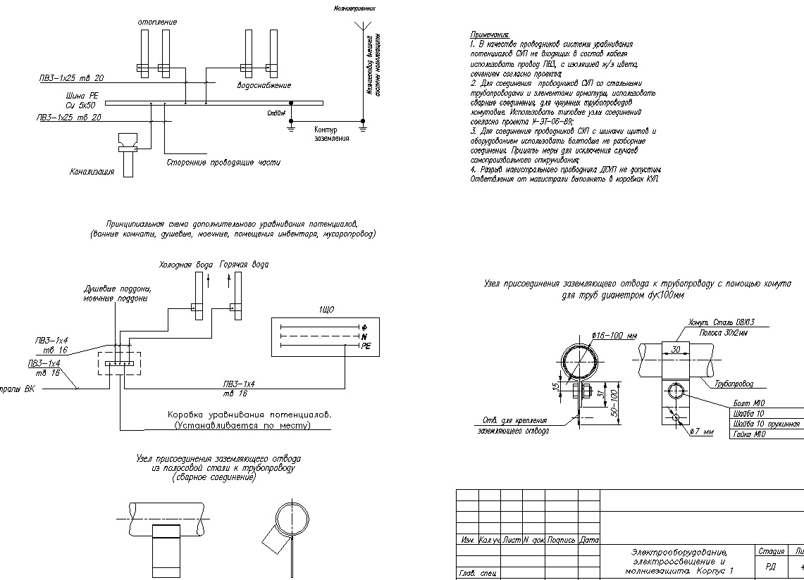
Diagram of the main equipotential bonding system of the building
Grounding and lightning protection. Roof plan.

Plan for entering cables from the trench into the building of 0.4 kV networks
Since electric current is a huge danger to life, the design and construction of multi-storey buildings and industrial facilities must be carried out in compliance with all the requirements for the installation of electrics. Since all electrical wiring of industrial and commercial buildings is laid with high-quality cables, it can only be performed by a qualified specialist. Not only the safety of electrical appliances, of which any apartment building has a large number, lighting, but also the lives of many people depends on the quality with which the design and execution are carried out.
Requirements for wiring installation
There are certain requirements that must be met when designing and wiring in a new building. They must be respected:
- During the installation of power cables.
- For lighting purposes and other circuits that have a voltage of no more than 1 kW of DC and AC and are laid from the inside and outside of objects in an installation wire in which all sections are insulated, as well as cables that do not have armor, have plastic and rubber insulation up to 16 mm2 ...
 Laying of non-armored cables, wires with and without protection through non-flammable walls and ceilings. Through walls and ceilings exposed to fire, installation must be done in a steel pipe. Openings in walls and openings in ceilings in an apartment building must have a frame, which will prevent their destruction during use. At the points where the cable and wire pass through walls, ceilings, or go out into the street, there must be no holes between cables, wires, boxes, openings and other structures. The gaps are easily closed with a mixture that has fireproof properties and can be easily removed, if necessary. You need to close the gaps on both sides of pipes, boxes and other things.
When the laying of metal pipes goes in an open manner, the places of passage through the fire barriers should be sealed with non-combustible material after the electrical wiring in the new building has been completed.
When installation cables with a maximum diameter of 4 mm 2 are exposed, they can be fixed to the wall cladding or plaster on casters. Brackets and hooks should only be attached to the base material of the walls. When the rollers are attached with wood grouses, washers made of metal and elastic material should be placed under the heads of the wood grouses; if the rollers are attached to metal, the washers must be elastic.
 To ensure the reliability of electrical installation, a long and safe service life of electrical wiring, during installation, it should be taken into account that:
- Exposed electrical wiring is laid on the wall under the ceiling, directly on the ceiling using trusses.
- Open wiring of unprotected cables on building foundations is laid along rollers and insulators, at a height of at least 2.5 m. You can reduce the distance to 2 m in places where there is no increased danger, and when the voltage is 42 V - in any room.
- In the production area, the supply to switches, starters, and sockets is protected from physical damage to a height of 1 meter from the floor or service area. For the household sector, residential, public buildings and electrical premises of organizations that have a commercial bias, the electrician does not protect all descents from physical impact.
- When placing wiring in other ways, such as: in a pipe, duct, cable, protected wire - there are no standards for the height of the laying. The organization of their protection is carried out only where there is a high probability of mechanical damage, in particular, these are driveways.
- In the open, the wires are laid in such a way that they are not strongly visible in the living area against the rest of the background. For this, if it is an apartment building, the wires are laid at the level of the cornice, along the slope of doors and windows.
- When crossing protected production and unprotected wires with a water or heating pipeline, a distance of at least 5 cm should be observed, with hidden laying. When flammable compounds pass through the pipeline - 10 cm or more. When it is not possible to observe the required indentation, it is required to provide additional protection of the wiring from physical damage.
- When laying cables parallel to pipelines, it is required to keep a distance of at least 10 cm, and from a pipeline with a flammable composition - 400 and more.
- The joints of the wires and their branches should be connected by welding, soldering, crimping in sleeves or using clamps in branch boxes.
Competent design already includes all these requirements.
Requirements for wiring in a production area

Since industrial electrical installation can include autonomous power devices, generators, laying a high-voltage line, assembling a transformer substation, etc., therefore, certain installation rules should be adhered to:
- In such buildings, in order for the electrical installation of industrial facilities to be carried out in accordance with all the rules, there must be an electrical panel that is equipped with a central switch.
- The power supply for lighting each room should be separate.
- Each electrical appliance should have its own circuit breaker to increase the overall safety of the production line.
- A prerequisite is the wiring of the cable in a metal pipe and special trays.
- In any workshop, it is mandatory to install a grounding bus, and all machines must have a solid grounding wire that is connected to the bus.
- The operation and maintenance of all electrical appliances must comply with all the rules of the PUE, the rules of protection against static electricity and other things, I turn on the lightning rod. This must be taken into account when the design is drawn up.
Video about installation in a new building