LED floodlights are a very popular thing today. But, like any electronics, spotlights break down relatively often.
Today's article will be devoted to repairing LED spotlights with your own hands.
All the theory on the design of LED spotlights and terminology, and here is practice for home craftsmen.
The spotlight is not on - where to start?
First of all, you need to make sure that 220 V power is supplied to the driver. This is Azy. Next, it remains to decide what is faulty - the LED driver or the LED matrix.
Checking the driver
Let me remind you that the word “driver” is a marketing ploy to designate a current source designed for a specific matrix with a certain current and power.
In order to test the driver without an LED (idle, without load), simply apply 220V to its input. A constant voltage should appear at the output, a value slightly greater than the upper limit indicated on the block.
For example, if the range of 28-38 V is indicated on the driver unit, then when it is turned on idle, the output voltage will be approximately 40V. This is explained by the principle of operation of the circuit - in order to maintain the current in a given range of ±5%, when the load resistance increases (idle = infinity), the voltage must also increase. Naturally, not to infinity, but to some upper limit.
However, this test method does not allow us to judge whether the LED driver is 100% serviceable.
The fact is that there are serviceable units that, when turned on idle, without load, either will not start at all, or will produce something unclear.
I suggest connecting a load resistor to the output of the LED driver to provide it with the desired operating mode. How to choose a resistor - according to Uncle Ohm's law, looking at what is written on the driver.

LED – driver 20 W. Stable output current 600 mA, voltage 23-35 V.
For example, if Output 23-35 VDC 600 mA is written, then the resistor resistance will be from 23/0.6=38 Ohms to 35/0.6=58 Ohms. We choose from a range of resistances: 39, 43, 47, 51, 56 Ohms. The power must be appropriate. But if you take 5 W, then it will be enough for a few seconds to check.
Attention! The driver output, as a rule, is galvanically isolated from the 220V network. However, you should be careful - cheap circuits may not have a transformer!
If, when connecting the required resistor, the output voltage is within the specified limits, we conclude that the LED driver is working.
Checking the LED matrix
For testing, you can use a laboratory power supply. We supply a voltage that is obviously lower than the nominal voltage. We control the current. The LED matrix should light up.
What to do if the power of the LED module is unknown
There are situations when there is an LED chip, but its power, current and voltage are unknown. Accordingly, it is difficult to buy it, and if it is working, it is not clear how to choose an adapter.
This was a big problem for me until I figured it out. I am sharing with you how to determine from the appearance of an LED assembly what voltage, power and current it is.
For example, we have a spotlight with the following LED assembly:
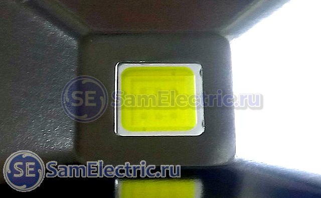
9 diodes. 10 W, 300 mA. In fact - 9 W, but this is within the margin of error.
The problem is that the LED matrices of the floodlights use 1 W diodes. The current of such diodes is 300...330 mA. Naturally, all this is approximately, within the margin of error, but in practice it works accurately.
In this matrix, 9 diodes are connected in series, they have one current (300 mA), and a voltage of 3 Volts. As a result, the total voltage is 3x9 = 27 Volts. For such matrices, you need a driver with a current of 300 mA, a voltage of approximately 27V (usually from 20 to 36V). The power of one such diode, as I said, is about 9 W, but for marketing purposes this spotlight will have a power of 10 W.
The 10 W example is a bit atypical due to the special arrangement of the LEDs.
What's new in the VK group? SamElectric.ru ?
Subscribe and read the article further:
Another example, more typical:

You already guessed it two horizontal rows of dots of 10 pieces each are LEDs. One strip is, offhand, 30 Volts, current 300 mA. Two strips connected in parallel - voltage 30 V, current twice as much, 600 mA.
A couple more examples:

Total - 50 W, current 300x5 = 1500 mA.

Total - 70 W, 300x7 = 2100 mA.
I think there is no point in continuing, everything is already clear.
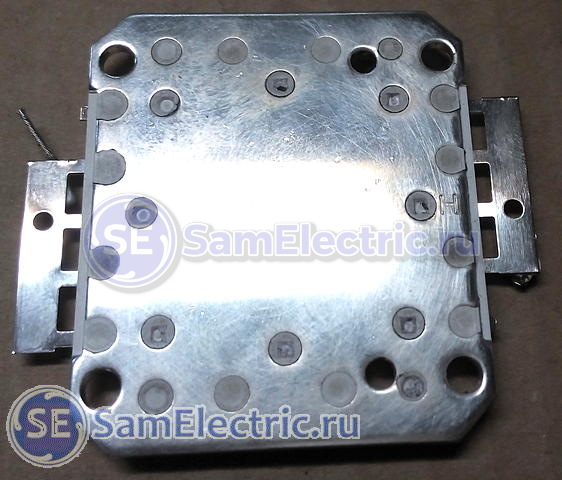
The situation is slightly different with LED modules based on discrete diodes. According to my calculations, one diode there usually has a power of 0.5 W. Here is an example of a GT50390 matrix installed in a 50 W floodlight:

LED floodlight Navigator, 50 W. LED module GT50390 – 90 discrete diodes
If, according to my assumptions, the power of such diodes is 0.5 W, then the power of the entire module should be 45 W. Its circuit will be the same, 9 lines of 10 diodes each with a total voltage of about 30 V. The operating current of one diode is 150...170 mA, the total current of the module is 1350...1500.
Anyone who has other thoughts on this matter is welcome to comment!
LED spotlight driver repair
It is better to start repairs by searching for the electrical circuit of the LED driver.
As a rule, LED spotlight drivers are built on a specialized MT7930 chip. In the article about the Design of Spotlights, I gave a photo of a board (not waterproof) based on this microcircuit, once again:
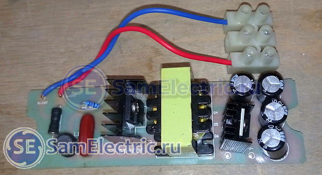
LED floodlight Navigator, 50 W. Driver. GT503F board

Attention! Information on driver circuits and a little more on repairs!
LED replacement
There are no special tricks when replacing the LED matrix, but you need to pay attention to the following things.
- Carefully remove old heat-conducting paste,
- Apply thermal conductive paste to the new LED. It is best to do this with a plastic card,
- fix the diode evenly, without distortions,
- remove excess paste,
- do not confuse the polarity,
- Do not overheat when soldering.
When repairing an LED module consisting of discrete diodes, first of all you need to pay attention to the integrity of the soldering. And then check each diode by applying a voltage of 2.3 - 2.8 V to it.
Where to get spare parts for repairs
If you need quick repairs, then the best thing, of course, is to run to the store across the street.
But if you are engaged in repairs on an ongoing basis, then it is better to look where it is cheaper. I recommend doing this on the well-known AliExpress website.
I'll end here. I encourage my colleagues to share their experiences and ask questions!
LED floodlights are a very popular thing today. But, like any electronics, spotlights break down relatively often. Today's article will be devoted to repairing LED spotlights with your own hands.
All the theory on the design of LED spotlights and terminology, and here is practice for home craftsmen.
The spotlight doesn't light up - where to start?
First of all, you need to make sure that 220 V power is supplied to the driver. This is Azy.
Checking the driver
Let me remind you that the word “driver” is a marketing ploy to designate a current source designed for a specific matrix with a certain current and power.
In order to test the driver without an LED (idle, without load), simply apply 220V to its input. A constant voltage should appear at the output, a value slightly greater than the upper limit indicated on the block.
For example, if the range of 28-38 V is indicated on the driver unit, then when it is turned on idle, the output voltage will be approximately 40V. This is explained by the principle of operation of the circuit - to maintain the current in a given range of ±5%, when the load resistance increases (idle = infinity), the voltage must also increase. Naturally, not to infinity, but to some upper limit.
However, this test method does not allow us to judge whether the LED driver is 100% serviceable.
The fact is that there are serviceable units that, when turned on idle, without load, either will not start at all, or will produce something unclear.
I suggest connecting a load resistor to the output of the LED driver to provide it with the desired operating mode. How to choose a resistor - according to Uncle Ohm's law, looking at what is written on the driver.
LED driver 20 W. Stable output current 600 mA, voltage 23-35 V.
For example, if Output 23-35 VDC 600 mA is written, then the resistor resistance will be from 23/0.6=38 Ohms to 35/0.6=58 Ohms. We choose from a range of resistances: 39, 43, 47, 51, 56 Ohms. The power must be appropriate. But if you take 5 W, then it will be enough for a few seconds to check.
Attention! The driver output, as a rule, is galvanically isolated from the 220V network. However, you should be careful - cheap circuits may not have a transformer!
If, when connecting the required resistor, the output voltage is within the specified limits, we conclude that the LED driver is working.
Checking the LED matrix
For testing, you can use a laboratory power supply. We supply a voltage that is obviously lower than the nominal voltage. We control the current. The LED matrix should light up.
What to do if the power of the LED module is unknown
There are situations when there is an LED chip, but its power, current and voltage are unknown. Accordingly, it is difficult to buy it, and if it is working, it is not clear how to choose an adapter.
This was a big problem for me until I figured it out. I am sharing with you how to determine from the appearance of an LED assembly what voltage, power and current it is.
For example, we have a spotlight with the following LED assembly:

9 diodes. 10 W, 300 mA. In fact - 9 W, but this is within the margin of error.
The problem is that the LED matrices of the floodlights use 1 W diodes. The current of such diodes is 300...330 mA. Naturally, all this is approximately, within the margin of error, but in practice it works accurately.
In this matrix, 9 diodes are connected in series, they have one current (300 mA), and a voltage of 3 Volts. As a result, the total voltage is 3x9 = 27 Volts. For such matrices, you need a driver with a current of 300 mA, a voltage of approximately 27V (usually from 20 to 36V). The power of one such diode, as I said, is about 9 W, but for marketing purposes this spotlight will have a power of 10 W.
The 10 W example is a bit atypical due to the special arrangement of the LEDs.
Another example, more typical:

You already guessed it two horizontal rows of dots of 10 pieces each are LEDs. One strip is, offhand, 30 Volts, current 300 mA. Two strips connected in parallel - voltage 30 V, current twice as much, 600 mA.
A couple more examples:
![]()
Total - 50 W, current 300x5 = 1500 mA.

Total - 70 W, 300x7 = 2100 mA.
I think there is no point in continuing, everything is already clear.
The situation is slightly different with LED modules based on discrete diodes. According to my calculations, one diode there usually has a power of 0.5 W. Here is an example of a GT50390 matrix installed in a 50 W floodlight:

LED floodlight Navigator, 50 W. LED module GT50390 - 90 discrete diodes
If, according to my assumptions, the power of such diodes is 0.5 W, then the power of the entire module should be 45 W. Its circuit will be the same, 9 lines of 10 diodes each with a total voltage of about 30 V. The operating current of one diode is 150...170 mA, the total current of the module is 1350...1500.
Anyone who has other thoughts on this matter is welcome to comment!
LED spotlight driver repair
It is better to start repairs by searching for the electrical circuit of the LED driver.
As a rule, LED spotlight drivers are built on a specialized MT7930 chip. In the article about the Design of Spotlights, I gave a photo of a board (not waterproof) based on this microcircuit, once again:
LED floodlight Navigator, 50 W. Driver. GT503F board

Attention! Information on driver circuits and a little more on repairs!
LED replacement
There are no special tricks when replacing the LED matrix, but you need to pay attention to the following things.
- Carefully remove old heat-conducting paste,
- Apply thermal conductive paste to the new LED. It is best to do this with a plastic card,
- fix the diode evenly, without distortions,
- remove excess paste,
- do not confuse the polarity,
- Do not overheat when soldering.

When repairing an LED module consisting of discrete diodes, first of all you need to pay attention to the integrity of the soldering. And then check each diode by applying a voltage of 2.3 - 2.8 V to it.
Where to get spare parts for repairs
If you need quick repairs, then the best thing, of course, is to run to the store across the street.
But if you are engaged in repairs on an ongoing basis, then it is better to look where it is cheaper. I recommend doing this on the well-known AliExpress website.
I provide several links for reference and examples, there is a lot of interesting information there, including descriptions, photos and selection.
LED matrices:
- Led Chip large selection from 10 to 100 W, from 48 to 360 rubles.
- Powerful LEDs.
Drivers for LED spotlights, for different powers:
- 30W waterproof DC power supply,
- 50W waterproof DC power supply,
- Waterproof Outdoor LED Drivers 10, 20, 30, 50W DC.
And who doesn’t want to repair, you can immediately order something ready-made:
LED street floodlights:
- Outdoor floodlights from 10 to 50 W,
- Waterproof flat floodlights from 10 to 100 W, LED Chip+Driver kit available.
To complete the picture, here is a video from my colleagues, they share their experience:
I'll end here. I encourage my colleagues to share their experiences and ask questions!
My previous job generously supplied me with corpses of LED lamps and fixtures. Without going into technical details, more than 99% of what is sold everywhere is outright slag, fundamentally incapable of working for any long time due to clearly insufficient, or even absent, cooling.
Here is an example of complete slag: a bullshit pure plastic “radiator”. the result is predictable: the LEDs are burnt out, blackening of the crystals is visible, and they self-soldered out
another dead guy
The “old-style” LED spotlights with a solid-cast aluminum radiator body were relatively well made, but they are rapidly disappearing from sale.

old style spotlight

old style spotlight
But, apparently, the sellers and Ketai people decided that so much lumini was too fat, and they optimized these spotlights. Now “new sample” floodlights with a plastic housing and a separate radiator are on sale everywhere.

New 30W floodlight
The cartridge was supplied for sizing purposes. The radiator has a fin area of approximately 200 sq.cm. The result is predictable: the heatsink heats up around +100 degrees, rapid degradation and failure of the LEDs
![]()
Guts floodlight 30W
Please note: there are 60pcs of 0.5W LEDs type 5630. diodes are used 100%. Reserve by mode? what nonsense, have not heard. And my electronics teacher back in the 80s used to say that those who use components at >60% of the limiting modes are either idiots or greedy bourgeois.
Here the circuit design of the emitter is as follows: 2 parallel groups of 30 serial 5630. The forward voltage is around 90V at +25g r, and the current is 300mA.
The LEDs are mounted on a luminous board, which is screwed only at the corners. The fit is loose.
the result is in the photo. In a measly 100 operating hours, the phosphor had already become very black, several diodes burned out, burning black holes in the phosphor. The driver also died. I re-connected the groups of LEDs in series, the driver was down-graded to a stupid capacitor one.

emitter large
It was experimentally found that such a radiator is capable of maintaining a reasonable temperature on the crystals in the region of +80°C and +60°C on the radiator, with only 1/3 of the nominal power of the spotlight. This is what I did, the current was reduced by three times.
The picture is approximately the same for other powers of spotlights of this type: terrible overheating and rapid dying
morality? Avoid purchasing such “new style” floodlights; if possible, look for solid cast “old style” floodlights.
By the way, pay attention to the drivers of different spotlights. They do not have a class capacitor in the rectifier. This is how manufacturers fight for a decent cosine phi. Needless to say, the 100Hz output ripple is enormous. Output capacitors do not help. Do not use such spotlights where you work for a long time, protect your eyes. At a minimum, it is useful to add electrolyte to the rectifier, at least 10 µF for every 10 W
Also note that all drivers, and those of LED lamps too, are made according to the “step-down” scheme, i.e. there is not a transformer, but a choke, and there is no isolation from the network! Be extremely careful! The chip-to-substrate insulation is clearly not designed for mains voltage.

LED floodlight drivers
Power
The power of the driver must match the power of the spotlight, or more precisely, the matrix in the spotlight. Do not rely on the power indicated on the body of the spotlight! We have had spotlights brought to us for repair many times, proudly labeled 50W in half a body with a 30-watt driver and matrix inside. Installing a 50-watt driver in such a product will not end well. It is imperative to read the labeling of the burnt driver.
Dimensions
The driver must physically fit inside the LED floodlight. And you still need to lay the wires.
We have the exact driver sizes listed on our website.
Driver output current value
The output current value is always indicated on the driver housing. This is the current that the driver will supply to the matrix. This value varies from approximately 300mA to 3000mA and must match the matrix supply current. Deviations of more than 5% are unacceptable.
Output voltage range
The driver output voltage range is the two voltage values within which the driver attempts to stabilize the current.
Numbers can range from 20 to 150 volts.
This range must coincide with the corresponding characteristic of the matrix, or, if it is unknown, the range of output voltages of the burnt driver.
This parameter does not have to match as closely as the current value, but there should be an approximate match.
Input voltage - 220 volts
We produce different drivers for LED spotlights, not only for 220 volts. Therefore, when purchasing a driver, make sure that you have a driver for the input voltage you need - all drivers presented in this section are designed for 220, 127 and 110 volt networks.
For those who haven’t read it, let me remind you briefly. Recently, a powerful 120 W LED floodlight was brought in for repairs; it only worked for a year. As it turned out, his driver burned out. And there I started whining about the fragility of switching power supplies and wondered about finding a simpler and more reliable solution. Today I decided to assemble and test the operation of a circuit with a quenching capacitor. A similar circuit is widely used to power LED spotlights.
Preliminarily calculated the capacity of the quenching capacitor using the well-known formula

For the calculation I took the following parameters:
Uc (mains voltage) = 220 V;
U (voltage at the input of the diode bridge) = 60 V;
I (nominal LED current) = 1.8 A;
According to calculations, it turned out that a capacitor with a capacity of 27 μF is needed. I went through the bins, collected all sorts of different capacitors to provide the required capacity, and also experimented with the deviation of the capacity from the calculated value. To avoid misunderstandings, the capacitance of all capacitors was measured with an E7-16 immittance meter.


Despite the venerable age of some specimens, the capacity practically corresponded to the specified one.

I soldered the circuit. In order not to bother too much, I used the power part from the computer power supply board. The result is this design

It was interesting to find out to what extent the current will change when the input voltage deviates by 20% from the nominal value with different values of the quenching capacitor capacitance. The experiments were carried out with LEDs preheated for 30 minutes. The measurement results were tabulated and presented in graphical form. During the measurement process, the voltage on capacitor C2 varied within 58 V...62, I decided not to include these values in the table due to their insignificant change.

The graphs turned out to be linear

The native driver ensured that the current flowing through the LEDs was maintained at a level of 1.8 A. According to various sources, the rated current of a 60 W LED ranges from 1.8 to 2 A, different sellers indicate different currents. We will assume that a current above 1.8 A is undesirable.
If you choose a capacitor with a capacity of 24 μF, then when the input voltage increases to 260 V, the current through the LEDs will not exceed the rated value. In normal mode, with an input voltage of 220 V, a current of 1.5 A is provided, which corresponds to a power consumption of 90 W. At a rated current of 1.8 A, the calculated power is about 110 W. Thus, with an input voltage of 220 V, we have a power reduction of 20 W (18%) relative to the nominal value. On the one hand, a lower current value increases the service life of the LED, but leads to a decrease in the brightness of the glow, although this is not particularly noticeable to the eye. It would be nice to measure the brightness with an appropriate device, but it is not available.
16.03.2018
For those who haven’t read it, let me remind you briefly. Recently, a powerful 120 W LED floodlight was brought in for repairs; it only worked for a year. As it turned out, his driver burned out. And there I started whining about the fragility of the power supply and wondered about finding a simpler and more reliable solution. Today I decided to assemble and test the operation of a circuit with a quenching capacitor. A similar circuit is widely used to power LED spotlights.
Preliminarily calculated the capacity of the quenching capacitor using the well-known formula
For the calculation I took the following parameters:
Uc (mains voltage) = 220 V;
U (voltage at the input of the diode bridge) = 60 V;
I (nominal LED current) = 1.8 A;
According to calculations, it turned out that a capacitor with a capacity of 27 μF is needed. I went through the bins, collected all sorts of different capacitors to provide the required capacity, and also experimented with the deviation of the capacity from the calculated value. To avoid misunderstandings, the capacitance of all capacitors was measured with an E7-16 immittance meter.


Despite the venerable age of some specimens, the capacity practically corresponded to the specified one.

I soldered the circuit. In order not to bother too much, I used the power part from the computer power supply board. The result is this design

It was interesting to find out to what extent the current will change when the input voltage deviates by 20% from the nominal value with different values of the quenching capacitor capacitance. The experiments were carried out with LEDs preheated for 30 minutes. The measurement results were tabulated and presented in graphical form. During the measurement process, the voltage on capacitor C2 varied within 58 V...62, I decided not to include these values in the table due to their insignificant change.

The graphs turned out to be linear

The native driver ensured that the current flowing through the LEDs was maintained at a level of 1.8 A. According to various sources, the rated current of a 60 W LED ranges from 1.8 to 2 A, different sellers indicate different currents. We will assume that a current above 1.8 A is undesirable.
If you choose a capacitor with a capacity of 24 μF, then when the input voltage increases to 260 V, the current through the LEDs will not exceed the rated value. In normal mode, with an input voltage of 220 V, a current of 1.5 A is provided, which corresponds to a power consumption of 90 W. At a rated current of 1.8 A, the calculated power is about 110 W. Thus, with an input voltage of 220 V, we have a power reduction of 20 W (18%) relative to the nominal value. On the one hand, a lower current value increases the service life of the LED, but leads to a decrease in the brightness of the glow, although this is not particularly noticeable to the eye. It would be nice to measure the brightness with an appropriate device, but it is not available.
LED floodlights are a very popular thing today. But, like any electronics, spotlights break down relatively often. Today's article will be devoted to repairing LED spotlights with your own hands.
All the theory on the design of LED spotlights and terminology, and here is practice for home craftsmen.
The spotlight doesn't light up - where to start?
First of all, you need to make sure that 220 V power is supplied to the driver. This is Azy.
Checking the driver
Let me remind you that the word “driver” is a marketing ploy to designate a current source designed for a specific matrix with a certain current and power.
In order to test the driver without an LED (idle, without load), simply apply 220V to its input. A constant voltage should appear at the output, a value slightly greater than the upper limit indicated on the block.
For example, if the range of 28-38 V is indicated on the driver unit, then when it is turned on idle, the output voltage will be approximately 40V. This is explained by the principle of operation of the circuit - to maintain the current in a given range of ±5%, when the load resistance increases (idle = infinity), the voltage must also increase. Naturally, not to infinity, but to some upper limit.
However, this test method does not allow us to judge whether the LED driver is 100% serviceable.
The fact is that there are serviceable units that, when turned on idle, without load, either will not start at all, or will produce something unclear.
I suggest connecting a load resistor to the output of the LED driver to provide it with the desired operating mode. How to choose a resistor - according to Uncle Ohm's law, looking at what is written on the driver.

LED driver 20 W. Stable output current 600 mA, voltage 23-35 V.
For example, if Output 23-35 VDC 600 mA is written, then the resistor resistance will be from 23/0.6=38 Ohms to 35/0.6=58 Ohms. We choose from a range of resistances: 39, 43, 47, 51, 56 Ohms. The power must be appropriate. But if you take 5 W, then it will be enough for a few seconds to check.
Attention! The driver output, as a rule, is galvanically isolated from the 220V network. However, you should be careful - cheap circuits may not have a transformer!
If, when connecting the required resistor, the output voltage is within the specified limits, we conclude that the LED driver is working.
Checking the LED matrix
For testing, you can use a laboratory power supply. We supply a voltage that is obviously lower than the nominal voltage. We control the current. The LED matrix should light up.
What to do if the power of the LED module is unknown
There are situations when there is an LED chip, but its power, current and voltage are unknown. Accordingly, it is difficult to buy it, and if it is working, it is not clear how to choose an adapter.
This was a big problem for me until I figured it out. I am sharing with you how to determine from the appearance of an LED assembly what voltage, power and current it is.
For example, we have a spotlight with the following LED assembly:

9 diodes. 10 W, 300 mA. In fact - 9 W, but this is within the margin of error.
The problem is that the LED matrices of the floodlights use 1 W diodes. The current of such diodes is 300...330 mA. Naturally, all this is approximately, within the margin of error, but in practice it works accurately.
In this matrix, 9 diodes are connected in series, they have one current (300 mA), and a voltage of 3 Volts. As a result, the total voltage is 3x9 = 27 Volts. For such matrices, you need a driver with a current of 300 mA, a voltage of approximately 27V (usually from 20 to 36V). The power of one such diode, as I said, is about 9 W, but for marketing purposes this spotlight will have a power of 10 W.
The 10 W example is a bit atypical due to the special arrangement of the LEDs.
Another example, more typical:

You already guessed it two horizontal rows of dots of 10 pieces each are LEDs. One strip is, offhand, 30 Volts, current 300 mA. Two strips connected in parallel - voltage 30 V, current twice as much, 600 mA.
A couple more examples:
![]()
Total - 50 W, current 300x5 = 1500 mA.

Total - 70 W, 300x7 = 2100 mA.
I think there is no point in continuing, everything is already clear.
The situation is slightly different with LED modules based on discrete diodes. According to my calculations, one diode there usually has a power of 0.5 W. Here is an example of a GT50390 matrix installed in a 50 W floodlight:

LED floodlight Navigator, 50 W. LED module GT50390 - 90 discrete diodes
If, according to my assumptions, the power of such diodes is 0.5 W, then the power of the entire module should be 45 W. Its circuit will be the same, 9 lines of 10 diodes each with a total voltage of about 30 V. The operating current of one diode is 150...170 mA, the total current of the module is 1350...1500.
Anyone who has other thoughts on this matter is welcome to comment!
LED spotlight driver repair
It is better to start repairs by searching for the electrical circuit of the LED driver.
As a rule, LED spotlight drivers are built on a specialized MT7930 chip. In the article about the Design of Spotlights, I gave a photo of a board (not waterproof) based on this microcircuit, once again:
LED floodlight Navigator, 50 W. Driver. GT503F board

Attention! Information on driver circuits and a little more on repairs!
LED replacement
There are no special tricks when replacing the LED matrix, but you need to pay attention to the following things.
- Carefully remove old heat-conducting paste,
- Apply thermal conductive paste to the new LED. It is best to do this with a plastic card,
- fix the diode evenly, without distortions,
- remove excess paste,
- do not confuse the polarity,
- Do not overheat when soldering.

When repairing an LED module consisting of discrete diodes, first of all you need to pay attention to the integrity of the soldering. And then check each diode by applying a voltage of 2.3 - 2.8 V to it.
Where to get spare parts for repairs
If you need quick repairs, then the best thing, of course, is to run to the store across the street.
But if you are engaged in repairs on an ongoing basis, then it is better to look where it is cheaper. I recommend doing this on the well-known AliExpress website.
I provide several links for reference and examples, there is a lot of interesting information there, including descriptions, photos and selection.
LED matrices:
- Led Chip large selection from 10 to 100 W, from 48 to 360 rubles.
- Powerful LEDs.
Drivers for LED spotlights, for different powers:
- 30W waterproof DC power supply,
- 50W waterproof DC power supply,
- Waterproof Outdoor LED Drivers 10, 20, 30, 50W DC.
And who doesn’t want to repair, you can immediately order something ready-made:
LED street floodlights:
- Outdoor floodlights from 10 to 50 W,
- Waterproof flat floodlights from 10 to 100 W, LED Chip+Driver kit available.
To complete the picture, here is a video from my colleagues, they share their experience:
I'll end here. I encourage my colleagues to share their experiences and ask questions!
I decided to post some of the secrets of my work. Today I will write how to become a Russian manufacturer of LED equipment and what the price of the product consists of.
This is a construction set. It includes body parts, a driver and a diode matrix. The case is bought in China. A copying machine has already been launched there to produce them, and the housing is inexpensive. Chinese bodies suck at painting, so we repaint them to suit our conditions. I didn’t film the painting process; in fact, it’s a regular polymer painting. This coloring distinguishes our spotlights from Chinese consumer goods.

Apply thermal paste to the inside of the case. Thermal paste will improve the heat transfer between the diode and the housing.
We take good thermal paste. It will not become stiff from heating and the diode will be well cooled.

This is the matrix itself. The manufacturer claims that it is assembled using crystals from the American company BRIDGELUX. These crystals are clean and bright. The nominal light output of such a matrix is 2200 lumens.
Lumen, lumen, lum is a unit of measurement of luminous flux. A regular 40 W light bulb produces at most 400 lumens. This means that its efficiency is 10 lumens per watt. This diode produces 110 lumens from 1 watt. However, in reality it is a little less, but more on that later.
Since the white light in this diode is produced by passing blue light (it is simply the most intense) through a yellow phosphor, the manufacturer paid special attention to it. If the phosphor is of poor quality, then it loses its properties over time. In fact, it is clear that the diode begins to turn blue. The blue color partially passes through the phosphor and then it seems that the light has become cold. Pay attention to the Chinese running lights on cars - they shine with a bluish light.

Firmly press the diode to the surface. Thermal paste is very easily soiled, so be careful not to smear the surface of the diode.

We remove the excess paste and screw the diode to the body.
The peculiarity of this diode is 20 single-wire points connected by gold threads. Some assemblers and manufacturers install similar diodes with 16 points and declare them to be 20-watt. The price of such a diode is lower, but it also produces worse light.

Cover the top with a decorative reflector. In fact, it is only needed for beauty. The diode itself shines at an angle of 120-140 degrees.

We place a gasket in the grooves of the housing. I use silicone ones. They are durable and not afraid of frost.

Press the gasket with glass

The shining part of the spotlight is ready!

We begin to assemble the power module. We put on silicone rings.

Install the bottom cover of the driver compartment housing and the driver itself.
There are a great variety of drivers. The more complex the driver, the longer the life of the diode. This driver stabilizes the current and voltage, even if the voltage in the network jumps from 80 to 280 volts. This will not be reflected in the glow.

We clean the PVS cable.

According to the inscriptions on the board, we connect to the terminal block. By the way, the block is the difference between a professional driver. The wire can be connected directly and of the desired cross-section. In Chinese consumer goods, this is all sealed and filled.

We choose the round section because it will fit more tightly into the nest.

The spotlight is reaching out to its creator. All that remains is to screw on the mounting arc and check for functionality.

Let there be light!

We do not overcharge the diodes, sacrificing brightness for durability. However, initially we use brighter diodes than our competitors. Roughly speaking, our diodes have a reserve of 30%.
The cosine φ (phi) is shown below. A value of more than 0.9 is considered an excellent indicator.
A low power factor leads to an increase in electricity losses in the electrical network.

Together with the driver, the spotlight consumes 24 watts.

As a result, we received a 24W LED spotlight with a luminous flux of about 2000 lumens. As practice has shown, the assembled spotlight has fairly low light degradation (about 5% per year). Its price is of course higher than Chinese consumer goods, therefore, it is used where reliability is valued.
My previous job generously supplied me with corpses of LED lamps and fixtures. Without going into technical details, more than 99% of what is sold everywhere is outright slag, fundamentally incapable of working for any long time due to clearly insufficient, or even absent, cooling.
Here is an example of complete slag: a bullshit pure plastic “radiator”. the result is predictable: the LEDs are burnt out, blackening of the crystals is visible, and they self-soldered out
another dead guy
The “old-style” LED spotlights with a solid-cast aluminum radiator body were relatively well made, but they are rapidly disappearing from sale.

old style spotlight

old style spotlight
But, apparently, the sellers and Ketai people decided that so much lumini was too fat, and they optimized these spotlights. Now “new sample” floodlights with a plastic housing and a separate radiator are on sale everywhere.

New 30W floodlight
The cartridge was supplied for sizing purposes. The radiator has a fin area of approximately 200 sq.cm. The result is predictable: the heatsink heats up around +100 degrees, rapid degradation and failure of the LEDs
![]()
Guts floodlight 30W
Please note: there are 60pcs of 0.5W LEDs type 5630. diodes are used 100%. Reserve by mode? what nonsense, have not heard. And my electronics teacher back in the 80s used to say that those who use components at >60% of the limiting modes are either idiots or greedy bourgeois.
Here the circuit design of the emitter is as follows: 2 parallel groups of 30 serial 5630. The forward voltage is around 90V at +25g r, and the current is 300mA.
The LEDs are mounted on a luminous board, which is screwed only at the corners. The fit is loose.
the result is in the photo. In a measly 100 operating hours, the phosphor had already become very black, several diodes burned out, burning black holes in the phosphor. The driver also died. I re-connected the groups of LEDs in series, the driver was down-graded to a stupid capacitor one.

emitter large
It was experimentally found that such a radiator is capable of maintaining a reasonable temperature on the crystals in the region of +80°C and +60°C on the radiator, with only 1/3 of the nominal power of the spotlight. This is what I did, the current was reduced by three times.
The picture is approximately the same for other powers of spotlights of this type: terrible overheating and rapid dying
morality? Avoid purchasing such “new style” floodlights; if possible, look for solid cast “old style” floodlights.
By the way, pay attention to the drivers of different spotlights. They do not have a class capacitor in the rectifier. This is how manufacturers fight for a decent cosine phi. Needless to say, the 100Hz output ripple is enormous. Output capacitors do not help. Do not use such spotlights where you work for a long time, protect your eyes. At a minimum, it is useful to add electrolyte to the rectifier, at least 10 µF for every 10 W
Also note that all drivers, and those of LED lamps too, are made according to the “step-down” scheme, i.e. there is not a transformer, but a choke, and there is no isolation from the network! Be extremely careful! The chip-to-substrate insulation is clearly not designed for mains voltage.

LED floodlight drivers
Although LED technology (including spotlights) is highly reliable, it also sometimes fails. Repairing LED spotlights allows you to eliminate most faults when you need to restore the functionality of the device. Repair work is relevant not only when the device does not shine brightly enough, but also if it completely stops working.
Operating principle and diagram
The LED spotlight (LED) includes the following components:
- LEDs (provide glow);
- drivers (control the operation of the device);
- frame;
- light diffuser (allows you to increase the efficiency of the lamp);
- lenses (control the shape, color and some other characteristics of the light flow).

The spotlight operates thanks to the coordinated actions of several of its components, including optics, power supply, drivers and heat sinks. The inside of the case contains light diodes, as well as small electronic components. The power supply supplies voltage to the LEDs, where the current is transformed into light output. Thanks to these actions, the device glows.
The figure below shows a standard electrical circuit for an electronic spotlight driver.

As for the operating principle of the driver, it does not differ on different spotlights. Power from the mains is supplied to the driver input, bypassing fuse F1. Next, filtering occurs using LC elements and rectification using a diode bridge. Smoothing is carried out by an electrolytic capacitor (C13). DC voltage (280 V) is generated at the capacitor terminals.
From the electrolytic capacitor, the voltage is directed through current-limiting resistors to the zener diode (D12) and pin No. 6 of the described microcircuit. The zener diode is responsible for the 9-volt power supply to the microcircuit, which is the main factor ensuring the functioning of the driver. From capacitor C13, current flows through the transformer winding (T1.1) through the lead part of the field-effect transistor (Q1).
Note! The amount of current flowing through the light diodes depends on the resistance parameters of the resistors on the microcircuit.
Signs of a spotlight malfunction
The most common signs of a malfunctioning spotlight:
- the lamp does not light up, although the power is turned on;
- the light diode flickers;
- the glow is too dim, as the lamp burns weakly - not at full power;
- the shade of the light flux has become unnatural.
Other signs may also be present, including physical damage to the structure of the case, deformation of the diode, burnt out electrical wiring.

Causes of failure
Possible reasons for the spotlight not working properly:
- Unstable electrical network (voltage drops beyond the operating current);
- short circuit of a phase to the device body or to neutral;
- incorrect connection;
- overvoltage;
- use of overcurrents.
In the event of these violations, the board on which drivers, voltage and current converters are installed, supplying power to the matrix crystals, may fail. Damage to 3 to 5 crystals in a floodlight matrix is allowed. If the number of faulty crystals is greater, the spotlight will not be able to operate with a sufficient degree of functionality and the matrix will need to be replaced.
Diagnostics
First of all, it is necessary to determine the cause of the LED spotlight malfunction. As an example, let's talk about checking the performance of a rectangular Volpe spotlight with a matrix including 9 diodes. The total power of the lamp is 10 W. The luminous flux is 750 lm.
The check is carried out in the following order:
- Inspect the wiring for physical integrity. Check for breaks, burnt insulation, or kinks in the cable. The purpose is to ensure that there are no breaks in the conductor.
- Check the device body, as well as the LED matrix for mechanical damage (deformation, chips, cracks).
- The next task is to check the input voltage by opening the back panel of the case. The input voltage should be 220V (AC). If there is no voltage, the cause of the breakdown is not in the lamp, but in the electrical circuit. Measurements are carried out with a standard multimeter. The output voltage is 12 V (DC).

- If there is no output voltage, the breakdown is looked for on the converter board. Inspect the contacts for oxidation, look for cracks in the tin coating in areas of soldering or burnt-out elements.
- If the above verification methods do not produce results, test the performance of the matrix.
Replacing parts
Eliminating broken wiring does not require special qualifications from a home technician. It is much more difficult to find and fix a breakdown on a printed circuit board, driver, voltage converter or matrix. You can't do this without special knowledge. You will also need the ability to work with diagnostic instruments and a soldering iron.
The following parts may be subject to repair or replacement:
- limiting capacitor;
- power unit;
- driver;
- matrix.
Current limiting capacitor
This component causes a malfunction when the spotlight lamp burns unevenly, constantly flickering. This problem is usually associated with the fact that manufacturers, in an effort to save money, install a current limiter that does not match the characteristics of the driver.
power unit
A common cause of malfunctioning of the spotlight is a breakdown of the power supply. In such a situation, you can purchase a new power supply or pick up this part from another device (for example, from a printer). If you decide to buy a new unit, it is recommended to take it with you to the store, since its technical characteristics are indicated on the case. To get the block, you first need to disassemble the spotlight.

Driver
Low-power models often lack a power supply. In such cases, an LED driver is used instead of a block. Since the diode is not able to receive power directly from the network (an alternating current other than the mains is needed), the driver is used. The device operates based on operating temperature and time, changing the output current to the LED.
To replace the driver, you should disassemble the spotlight to set the technical parameters of the driver, and then contact the store. Just as in the case of a power supply, you can select a suitable driver from another device.
Matrix
The most common cause of spotlight malfunction is excessive heating of the matrix, which leads to blown fuses. The spotlight is disassembled, after which the damaged matrix is taken out. To do this, unscrew the four screws and solder off the conductive parts. Next, apply a layer of thermal paste to the LED and solder the conductive parts back. The operation is completed by screwing the matrix into place.

In some cases, the wiring in the matrix goes through the holes in the substrate. It acts as a matrix radiator. In the transition areas, the wires must be covered with an insulating layer (primarily we are talking about the positive wire). This will avoid a short circuit to the device body.
Advice! Before replacing the matrix, you should clean the substrate and the area where it will be installed. It is recommended to treat these areas with a heat-conducting compound.
The shape of the matrix must not be disturbed. It is recommended to use only “original” screws so as not to damage the design. Also, do not forget about the polarity: the red wire is positive, the black or blue wire is negative, the green-yellow wire is directed to the body.
If at least 2-3 burnt-out diodes are detected, you should not wait for the matrix to burn out completely. In any case, the device is no longer able to function normally, as a result of which the drivers and voltage converter will soon fail.

Note! If the matrix does not work with a filled compound element, it cannot be restored.
Voltage converter circuit board
If, when checking the board, obvious signs of burnt-out elements are found, the device will need to be repaired. The figure below shows a converter circuit for a spotlight.

Before replacing non-functioning parts, you should ring the LEDs. First, one of the board legs is unsoldered, since ringing the soldered elements will not give the correct result. If necessary, burnt out parts are replaced with new ones.
Low power floodlight repair
As an example, let's look at the repair of the SDO01-10 floodlight. Device power - 10 W. An external inspection shows peeling of the protective coating on one of the floodlights. There are also dark spots on the light-emitting surface of the matrix.
Repairing a matrix with a damaged LED emitter is possible, but such a part is not cheap. The cost reaches 40-50% of the price of the entire spotlight. In addition, purchasing a new matrix presents another difficulty - most often there are no markings on the LEDs. As a result, it is not easy to determine the type of emitter.
To simplify the task, we install the spotlight driver from the burnt-out matrix to a lamp with a working matrix. On the old driver, the protective resistor burned out (its value is 1 Ohm), which indicates a breakdown of the diode in the diode bridge at the transition from the key resistor to the control resistor. However, replacing the driver did not restore the functionality of the spotlight.

After further testing, a break in the optical feedback pair was detected. Replacing the pair gave results - the lamp started working.
Repair of a powerful spotlight
The subject of consideration is the model of a powerful spotlight SDO01-30. Devices of this type are used for lighting large rooms (for example, industrial purposes).
First, we remove the back panel from the spotlight and visually inspect the condition of the radio components on the printed circuit board. We pay attention to elements that look suspicious (carbon deposits, deformations, etc.).
Next, we inspect the printed circuit board (pulling it out of the spotlight) from the semiconductor side. An inspection revealed the presence of a pair of burnt-out resistors: R8 (2 ohms) and R22 (1 ohms). Resistors with low resistance most often burn out due to the high current passing through them in the event of a breakdown of semiconductors or capacitors.

Next to the resistors is a field-effect transistor SFV4N65F. The ringing determined its malfunction. Since the spotlight circuit was not available, we find out the values of the resistors that burned out by disassembling a working lamp of the same model.
We unsolder the failed resistors, as well as the transistor. We replace them with new parts.
Some useful tips for repairing LED floodlights:
- When replacing the matrix, be sure to pay attention to the polarity.
- Be sure to remove the hardened heat-conducting paste under the matrix.
- The surface should be degreased with alcohol.
- When soldering, you do not need to overheat the surface. Soldering time is up to 2 seconds. If the matrix is overheated, the crystals will be destroyed or their new characteristics will not allow the spotlight to function normally.
- To repair a high-power spotlight, the knowledge used in repairing low-power lamps is sufficient. There are no special differences between devices of different power.
- If a matrix with a large number of diodes is not filled with a compound solution, the non-working diode will need to be replaced. To perform this operation, a micro-soldering iron is required. You need to work carefully so as not to overheat the crystals.
- If it is impossible to see the values on the burnt-out resistances, you cannot do without the instructions for the spotlight. It must contain the relevant data.
Anyone can fix a spotlight. However, to perform repair work, at least basic knowledge of electrical engineering is required, as well as skills in using a soldering iron and a multimeter. You also need the ability to read diagrams to understand the design of the spotlight.
Although LED technology is very reliable, it cannot be perfect and sometimes fails. Especially if you decide to save a lot and purchase one of the cheapest floodlights. So what to do if your LED floodlight, or even worse, stopped working altogether, and your warranty on the purchased product has expired, or did not start at all. It is quite possible that you purchased an uncertified product from a reliable store with a good reputation, and at your own peril and risk ordered the most affordable LED spotlight directly from China, through Aliexpress, for example? And now a far from cheap lighting device lies in front of you and blinks or does not shine at all, and you don’t know what to do? Don't give up. In this article we will tell you how to repair the device yourself.

In order to repair an LED processor with your own hands, you must confidently hold a multimeter (in the picture below) and a soldering iron in your hands. This is necessary in order to be able to determine the cause of the breakdown, and, in fact, ultimately eliminate it, returning the device to life.

Probable causes of failure and ways to eliminate them
Current limiting capacitor
So, first of all, you need to determine the cause of the malfunction of your device. If the spotlight turns on, but when turned on does not burn evenly, but flickers and blinks, the current-limiting capacitor C1 has probably failed. Many Chinese manufacturers make the mistake of using a current-limiting capacitor that does not match the parameters of the driver when trying to achieve maximum brightness from a not very powerful spotlight. A current-limiting capacitor at 400 volts rated operating voltage will do just fine.
power unit
Another common cause may be a failed power supply. There are two ways out of the situation - go to an electronics store, where they will help you choose a suitable power supply (its characteristics are indicated on it, therefore it is advisable to disassemble the spotlight and take the unit with you), or select a power supply (may be suitable from a scanner or printer).

The second option is possible, of course, only if you suddenly have unnecessary and non-working office equipment lying around that can serve as a power supply donor. Check the power supplies so that they are similar in parameters. An exact match is not necessary, but the parameters should not diverge too much. As mentioned earlier, if you have the skills to use tools and understand electronics, you can easily change the power supply yourself.
Driver
If a low-power spotlight needs repair, it is likely that it may not have its own power supply, and the function of changing currents in it is performed by the LED driver. Since the LED cannot be powered directly from the network, requiring an alternating current that differs from what the network can offer it, the floodlight uses a driver that takes into account the variation in the characteristics of the LED depending on the operating temperature and time, adjusting the output current supplied to the LED . It is this driver that can fail.

To replace it, you will need to disassemble the LED spotlight and find out the driver markings in order to buy or order a replacement. If you are a confident user of power tools, you can find a failed driver element and unsolder it and replace it. If you are repairing, most likely it will be quite easy for you to find the problem in the driver or find a similar driver and replace it. It will definitely be cheaper than buying or assembling a new spotlight from scratch.
Matrix burnout
Another option for failure of the design of your LED spotlight, in addition to a malfunction of the driver, power supply or other small elements involved in the current conversion process, may be the burnout of the LED matrix itself. If the LED itself fails, you need to find and purchase a diode with similar characteristics. After disassembling the spotlight, you will need to carefully uninstall the burnt matrix by unscrewing the four fastening screws and unsoldering the conductive elements. Then you will need to evenly and carefully apply a layer of thermal paste to the new diode, solder the current-carrying elements and carefully screw the matrix. It is necessary to take into account that the shape of the matrix must remain intact, that is, it is advisable to use the same screws that were originally used. They should not have conical heads, because if you use them, if you tighten them with a little more force, they can damage the matrix and all your work will be in vain.
Let's sum it up
To repair an LED spotlight yourself, you must at least have good skills in working with a soldering iron, testers and a multimeter, as well as understand circuit diagrams or be able to read them in order to find the cause of the malfunction, unsolder the faulty element and replace it.
If the driver or power supply in your spotlight fails, you can find a replacement and bring the lighting device back to life. Just like with the driver, a replacement can be made with an LED matrix - just buy an analogue with similar characteristics. If for some reason the device does not work after your manipulations, it probably makes sense to purchase a new one. But if you are confident in your abilities, you can always assemble an LED spotlight with your own hands - it will be easier to repair it in the future, or replace some elements, constantly extending the life of the device.