You can make simple electronic circuits for home use with your own hands, even without deep knowledge of electronics. In fact, at the everyday level, radio is very simple. Knowledge of the elementary laws of electrical engineering (Ohm, Kirchhoff), the general principles of operation of semiconductor devices, skills in reading circuits, and the ability to work with an electric soldering iron is quite enough to assemble a simple circuit.
Radio amateur workshop
No matter how complex the scheme may have to be completed, you must have a minimum set of materials and tools in your home workshop:
- Side cutters;
- Tweezers;
- Solder;
- Flux;
- Circuit boards;
- Tester or multimeter;
- Materials and tools for making the device body.
You should not purchase expensive professional tools and devices to begin with. An expensive soldering station or digital oscilloscope will be of little help to a novice radio amateur. At the beginning of your creative journey, the simplest instruments are sufficient, on which you need to hone your experience and skills.

Where to start
Do-it-yourself radio circuits for the home should not exceed the level of complexity that you have, otherwise it will only mean wasted time and materials. If you lack experience, it is better to limit yourself to the simplest schemes, and as you gain skills, improve them, replacing them with more complex ones.
Usually, most literature in the field of electronics for beginning radio amateurs gives a classic example of making the simplest receivers. This especially applies to classical old literature, which does not contain so many fundamental errors compared to modern literature.
Note! These schemes were designed for the enormous power of transmitting radio stations in the past. Today, transmitting centers use less power to transmit and try to move to shorter wavelengths. Don't waste time trying to make a working radio using a simple circuit.
Radio circuits for beginners should contain a maximum of two or three active elements - transistors. This will make it easier to understand the operation of the circuit and increase the level of knowledge.
What can be done
What can be done so that it is not difficult and can be used in practice at home? There can be many options:
- Apartment call;
- Christmas tree garland switch;
- Backlight for modding the computer system unit.

Important! You should not design devices that operate on household AC power until you have sufficient experience. This is dangerous both for life and for others.
Quite simple circuits have amplifiers for computer speakers, made on specialized integrated circuits. Devices assembled on their basis contain a minimum number of elements and require virtually no adjustment.
You can often find circuits that need basic modifications and improvements that simplify manufacturing and configuration. But this should be done by an experienced master so that the final version is more accessible to a beginner.
What to use for the design
Most literature recommends constructing simple circuits on circuit boards. Nowadays this is quite simple. There are a wide variety of circuit boards available with different hole and trace configurations.
The installation principle is that the parts are installed on the board in free spaces, and then the necessary pins are connected to each other by jumpers, as indicated on the circuit diagram.

With due care, such a board can serve as the basis for many circuits. The power of the soldering iron for soldering should not exceed 25 W, then the risk of overheating radio elements and printed conductors will be minimized.
The solder should be low-melting, like POS-60, and as a flux it is best to use pure pine rosin or its solution in ethyl alcohol.
Highly qualified radio amateurs can themselves develop a printed circuit board design and make it on foil material, on which they can then solder radio elements. The design developed in this way will have optimal dimensions.
Design of the finished structure
Looking at the creations of beginners and experienced craftsmen, one can come to the conclusion that assembling and adjusting the device is not always the most difficult part of the design process. Sometimes a properly functioning device remains a set of parts with soldered wires, not covered by any housing. Nowadays, you no longer have to worry about making a case, because on sale you can find all kinds of sets of cases of any configuration and size.

Before you start manufacturing the design you like, you should fully think through all the stages of the work: from the availability of tools and all radio elements to the design of the housing. It will be completely uninteresting if during the work it turns out that one of the resistors is missing, and there are no replacement options. It is better to carry out the work under the guidance of an experienced radio amateur, and, as a last resort, periodically monitor the manufacturing process at each stage.
Video
When studying electronics, the question arises of how to read electrical diagrams. The natural desire of a novice electronics engineer or radio amateur is to solder some interesting electronic device. However, at the initial stage, sufficient theoretical knowledge and practical skills are, as always, not enough. Therefore, the device is assembled blindly. And it often happens that a soldered device, on which a lot of time, effort and patience was spent, does not work, which only causes disappointment and discourages a novice radio amateur from getting involved in electronics, having never experienced all the delights of this science. Although, as it turns out, the scheme did not work due to a mere trivial mistake. It would take a more experienced radio amateur less than a minute to correct such an error.
This article provides useful recommendations that will help minimize the number of errors. They will help a novice radio amateur assemble various electronic devices that will work the first time.
Any radio-electronic equipment consists of individual radio components, soldered (connected) to each other in a certain way. All radio components, their connections and additional symbols are displayed on a special drawing. Such a drawing is called an electrical diagram. Each radio component has its own designation, which is correctly called conventional graphic designation, abbreviated as UGO. We will return to UGO later in this article.
 In principle, two stages can be distinguished in improving the reading of electrical circuits. The first stage is typical for installers of radio-electronic equipment. They simply assemble (solder) devices without delving into the purpose and operating principle of its main components. In fact, this is a boring job, although soldering is good, you still need to learn. Personally, I find it much more interesting to solder something that I fully understand how it works. There are many options for maneuvers. You understand which denomination, for example, is critical in this case, and which one can be neglected and replaced with another. Which transistor can be replaced with an analogue, and where should a transistor of the specified series be used only. Therefore, I personally prefer the second stage.
The second stage is inherent to developers of electronic equipment. This stage is the most interesting and creative, since one can improve endlessly in the development of electronic circuits.
Entire volumes of books have been written in this area, the most famous of which is “The Art of Circuit Design.” It is to this stage that we will strive to approach. However, this will require deep theoretical knowledge, but it’s all worth it.
Power supply designation
Any radio-electronic device is capable of performing its functions only in the presence of electricity. There are fundamentally two types of electricity sources: direct and alternating current. This article discusses sources exclusively. These include batteries or galvanic cells, rechargeable batteries, various types of power supplies, etc.
There are thousands of thousands of different batteries, galvanic cells, etc. in the world, which differ in both appearance and design. However, they are all united by a common functional purpose - to supply electronic equipment with direct current. Therefore, in the drawings of electrical circuits, sources are designated uniformly, but still with some minor differences.
It is customary to draw electrical circuits from left to right, that is, the same way as writing text. However, this rule is not always followed, especially by radio amateurs. But, nevertheless, this rule should be adopted and applied in the future.
 A galvanic cell or one battery, no matter “finger”, “pinky” or tablet type, is designated as follows: two parallel lines of different lengths. A longer dash indicates the positive pole – plus “+”, and a shorter one – minus “-”.
Also, for greater clarity, battery polarity signs may be indicated. The galvanic cell or battery has a standard letter designation G.
 However, radio amateurs do not always adhere to such encryption and often instead G write a letter E, which means that this galvanic cell is a source of electromotive force (EMF). The EMF value may also be indicated next to it, for example 1.5 V.
Sometimes, instead of a picture of the power supply, only its terminals are shown.
A group of voltaic cells that can be recharged repeatedly, battery. In the drawings of electrical circuits they are designated similarly. Only between the parallel lines is a dotted line and a letter designation is used G.B.. The second letter just means “battery”.
Designation of wires and their connections on diagrams
Electrical wires perform the function of combining all electronic elements into a single circuit. They act as a “pipeline” - they supply electronic components with electrons. Wires are characterized by many parameters: cross-section, material, insulation, etc. We will deal with installation flexible wires.
On printed circuit boards, conductive paths serve as wires. Regardless of the type of conductor (wire or track), in the drawings of electrical circuits they are designated in the same way - a straight line.
For example, in order to light an incandescent lamp, it is necessary to supply voltage from the battery using connecting wires to the light bulb. Then the circuit will be closed and a current will begin to flow in it, which will cause the filament of the incandescent lamp to heat up until it glows.

The conductor should be denoted by a straight line: horizontal or vertical. According to the standard, wires or live paths can be depicted at an angle of 90 or 135 degrees.
In branched circuits, conductors often intersect. If an electrical connection is not formed, then a dot is not placed at the intersection.

Common wire designation
In complex electrical circuits, in order to improve the readability of the diagram, the conductors connected to the negative terminal of the power source are often not shown. Instead, they use signs indicating the negative wire, which is also called generally th or weight or chassis or s earth.

Next to the grounding sign, especially in English-language circuits, the inscription GND is often written, abbreviated from GRAUND - Earth.

However, you should know that the common wire does not have to be negative; it can also be positive. It was especially often mistaken for the positive common wire in old Soviet circuits, which predominantly used transistors p— n— p structures.
Therefore, when they say that the potential at some point in the circuit is equal to some voltage, this means that the voltage between the indicated point and the “minus” of the power supply is equal to the corresponding value.
For example, if the voltage at point 1 is 8 V, and at point 2 it is 4 V, then you need to install the positive probe of the voltmeter at the corresponding point, and the negative probe to the common wire or negative terminal.

This approach is quite often used, since it is very convenient from a practical point of view, since it is enough to indicate only one point.
This is especially often used when setting up or adjusting radio-electronic equipment. Therefore, learning to read electrical circuits is much easier by using potentials at specific points.
Conventional graphic designation of radio components
The basis of any electronic device is radio components. These include LEDs, transistors, various microcircuits, etc. To learn how to read electrical circuits, you need to have a good knowledge of the conventional graphic symbols of all radio components.
For example, consider the following drawing. It consists of a battery of galvanic cells G.B.1 , resistor R1 and LED VD1 . The conventional graphic designation (UGO) of the resistor looks like a rectangle with two terminals. In the drawings it is indicated by the letter R, followed by its serial number, for example R1 , R2 , R5 etc.

Since an important parameter of a resistor, in addition to resistance, is , its value is also indicated in the designation.
The LED UGO has the shape of a triangle with a line at its apex; and two arrows, the tips of which are directed from the triangle. One terminal of the LED is called the anode, and the second is called the cathode.

An LED, like a “regular” diode, passes current in only one direction - from the anode to the cathode. This semiconductor device is designated VD, and its type is indicated in the specification or in the description of the circuit. The characteristics of a particular type of LED are given in reference books or “datasheets”.
How to read electrical diagrams for real
Let's return to the simplest circuit consisting of a battery of galvanic cells G.B.1 , resistor R1 and LED VD1 .
As we see, the circuit is closed. Therefore, electric current flows in it I, which has the same meaning since all elements are connected in series. Direction of electric current I from the positive terminal G.B.1 through a resistor R1 , Light-emitting diode VD1 to the negative terminal.
The purpose of all elements is quite clear. The ultimate goal is to light up the LED. However, so that it does not overheat and fail, the resistor limits the amount of current.
The voltage value, according to Kirchhoff’s second law, may differ on all elements and depends on the resistance of the resistor R1 and LED VD1 .
If you measure the voltage with a voltmeter R1 And VD1 , and then add the resulting values, then their sum will be equal to the voltage at G.B.1 : V1 = V2 + V3 .

Let's assemble a real device using this drawing.

Adding radio components
Consider the following circuit, consisting of four parallel branches. The first one is just a battery G.B.1, voltage 4.5 V. Normally closed contacts are connected in series in the second branch K1.1 electromagnetic relay K1 , resistor R1 and LED VD1 . Further along the drawing there is a button S.B.1 .

The third parallel branch consists of an electromagnetic relay K1 shunted in the opposite direction by a diode VD2 .
The fourth branch has normally open contacts K1.2 and boozer B.A.1 .
There are elements here that we have not previously considered in this article: S.B.1 – this is a button without fixing the position. While it is pressed, the contacts are closed. But as soon as we stop pressing and remove our finger from the button, the contacts open. Such buttons are also called tact buttons.

The next element is an electromagnetic relay K1 . Its operating principle is as follows. When voltage is applied to the coil, its open contacts close and its closed contacts open.

All contacts that correspond to the relay K1 , are designated K1.1 , K1.2 etc. The first digit indicates that they belong to the corresponding relay.
Boozer
WITH The next element, previously unknown to us, is the boozer. The buzzer can to some extent be compared to a small speaker. When an alternating voltage is applied to its terminals, a sound of the corresponding frequency is heard. However, in our circuit there is no alternating voltage. Therefore, we will use an active buzzer, which has a built-in alternating current generator.

Passive Boozer – for alternating current .
Active boozer – for direct current.
The active buzzer has a polarity, so you should adhere to it.
Now we can look at how to read an electrical diagram as a whole.
In the original state the contacts K1.1 are in a closed position. Therefore, current flows through the circuit from G.B.1 through K1.1 , R1 , VD1 and returns again to G.B.1 .
When the button is pressed S.B.1 its contacts close and a path is created for current to flow through the coil K1 . When the relay has received power its normally closed contacts K1.1 open, and normally closed contacts K1.2 are closed. As a result, the LED goes out VD1 and a buzzer sound is heard B.A.1 .
Now let's return to the parameters of the electromagnetic relay K1 . The specification or drawing must indicate the series of the relay used, for example H.L.S.‑4078‑ DC5 V. Such a relay is designed for a nominal operating voltage of 5 V. However, G.B.1 = 4.5 V, but the relay has a certain operating range, so it will work well at a voltage of 4.5 V.
To select a buzzer, it is often enough to know only its voltage, but sometimes you also need to know the current. You should also not forget about its type - passive or active.
Diode VD2 series 1 N4148 designed to protect elements that open the circuit from overvoltage. In this case, you can do without it, since the circuit is opened by a button S.B.1 . But if it is opened by a transistor or thyristor, then VD2 must be installed.
Learning to read circuits with transistors
In this drawing we see VT1 and engine M1 . To be specific, we will use a transistor of the type 2 N2222 who works in .

In order for the transistor to open, you need to apply a positive potential to its base relative to the emitter - for n— p— n type; For p— n— p type you need to apply a negative potential relative to the emitter.
Button S.A.1 with fixation, that is, it retains its position after pressing. Engine M1 direct current.
In the initial state, the circuit is open by contacts S.A.1 . When the button is pressed SA1 multiple paths for current flow are created. The first way is “+” G.B.1 - contacts S.A.1 – resistor R1 – transistor base-emitter junction VT1 – «-» G.B.1 . Under the influence of current flowing through the base-emitter junction, the transistor opens and a second current path is formed - “+” G.B.1 – S.A.1 – relay coil K1 – collector-emitter VT1 – «-» G.B.1 .
Having received power, the relay K1 closes its open contacts K1.1 in the engine circuit M1 . This creates a third path: "+" G.B.1 – S.A.1 – K1.1 – M1 – «-» G.B.1 .
Now let's summarize everything. In order to learn to read electrical circuits, at first it is enough just to clearly understand the laws of Kirchhoff, Ohm, electromagnetic induction; methods of connecting resistors, capacitors; You should also know the purpose of all elements. Also, at first, you should assemble those devices for which there are the most detailed descriptions of the purpose of individual components and assemblies.
My very useful course for beginners will help you understand the general approach to developing electronic devices from drawings, with many practical and visual examples. After completing this course, you will immediately feel that you have moved from a beginner to a new level.
A selection of simple and interesting circuits for beginner radio amateurs. The main emphasis of the proposed designs is on simplicity and understanding of the operation of the basics of electronics. In addition, various methods for testing basic radio-electronic components such as diodes, transistors and optocouplers are considered, and the operation of the latter is also considered.
In this article, in a simple and convenient form, you will master the skills of using a multimeter. You will learn about ways to test the main radio components from which we will assemble our first electronic homemade products. You will learn how to test the assembled circuit with a multimeter and check the functionality of the diode, transistor and capacitor.
In this article, novice radio amateurs will be able to get acquainted with the conventional graphic designation of various types of radio components in circuit diagrams, accepted in world amateur radio practice.
Simple schemes for beginner Arduinists |
A series of articles and training diagrams with amateur radio experiments on the Arduino board for beginners. Arduino is an amateur radio construction toy, from which, without a soldering iron, etching of printed circuit boards, etc., any beginner in electronics can assemble a full-fledged working device, suitable for professional prototyping and for amateur experiments in the study of electronics. And besides, Arduino is a useful electronic gadget in a smart household.
How a semiconductor device called a transistor works and works, why it is so often found in radio equipment and why it is almost never possible to do without it.
Magnetization indicator- An ordinary school compass is sensitive to the magnetic field. It is enough, say, to pass the magnetized end of a screwdriver in front of its arrow and the arrow will deflect. But, unfortunately, after this the arrow will swing for some time due to inertia. Therefore, it is inconvenient to use such a simple device for determining the magnetization of objects. The need for such a measuring device often arises. An indicator assembled from several parts turns out to be completely non-inertial and relatively sensitive to, for example, determine the magnetization of a razor blade or a watch screwdriver. In addition, such a device will be useful in school when demonstrating the phenomenon of induction and self-induction
Alternating electromagnetic field indicator A magnetic field is formed around a conductor carrying current. If you turn on, say, a table lamp, then such a field will be around the wires supplying the mains voltage to the lamp. Moreover, the field will be variable, changing with a network frequency of 50 Hz. True, the field strength is low, and it can only be detected with a sensitive indicator
Hidden Wiring Finder. An alternating electromagnetic field can be detected using electronic devices; let's get acquainted with a more sensitive indicator that can detect the weak field of network wires through which alternating current flows. We will talk about finding hidden wiring in your apartment. This indicator will warn of damage to network wires when drilling holes in the wall
Power consumption indicator The “readings” of the previous indicators depend on the magnetic intensity. or an electric (as in the last indicator) field created by current flowing through the wires. The greater the current, the stronger the field. But current is nothing more than a characteristic of the power consumed by the load from the AC network. Therefore, it is not difficult to guess that an indicator, for example with an inductive sensor, can be used in circuits for monitoring and measuring power consumption. In addition, such an indicator circuit, installed near the front door, will signal before leaving the apartment that appliances have been left on. The best place to install the sensor is at the entrance of wires into the apartment, near the junction box. Therefore, the total current of all consumers connected to any socket in the apartment flows here. True, the alternating voltage at the terminals of the sensor coil will be small, and an amplifier will be needed
Telephone call indicator light If the TV is playing loudly in the room, the phone call may not be heard. This is where you need a light signaling device that will turn on the indicator circuit as soon as there is a phone call.
The basis of the automatic signaling device circuit is a sensor that responds to telephone calls, made on an inductance coil. It is located next to the telephone set, so its turns are in the magnetic field of the ringing bell electromagnet. The call signal induces an alternating emf in the sensor coil.
"Silent" sound scheme for beginners Sometimes you want to listen to the radio or watch TV without disturbing others? Of course, plug in headphones into the additional jacks, you say. That's right, but such a communication system is inconvenient - the connecting wire of the headphones does not allow you to move a significant distance, much less walk around the room. All this can be avoided if you use a “wireless” communication circuit consisting of a transmitter and receiver.
Electronic mine Using the principle of inductive coupling, you can assemble with your own hands an interesting circuit used in organizing competitions to search for “mines” - miniature transmitters hidden in the ground or indoors, operating at an audio frequency.
Each such “mine” is a multivibrator circuit operating at a frequency of approximately 1000 Hz. A power amplifier with an inductor as a load is included in the emitter circuit of the transistor of the multivibrator circuit. An electromagnetic field of sound frequency is formed around it
Intermittent siren Let's start with the simplest design, simulating the sound of a siren. There are single-tone sirens, which emit a sound of one tone, intermittent ones, when the sound smoothly increases and decreases, and then is interrupted or becomes single-tone, and two-tone ones, in which the tone of the sound periodically changes abruptly.
The intermittent electronic siren circuit is assembled using transistors VT 1 and VT 2 using an asymmetrical multivibrator circuit. The simplicity of the generator circuit is explained by the use of transistors of different structures, which made it possible to do without many of the parts necessary in the circuit for constructing a multivibrator using transistors of the same structure.
Two-tone siren. Looking at the circuit of this simulator, it is easy to notice an already familiar unit - a generator assembled on transistors VT 3 and VT 4. The previous simulator was assembled using this circuit. Only in this case the multivibrator does not operate in standby mode, but in normal mode. To do this, a bias voltage is applied to the base of the first transistor (VT 3) from the divider R 6 R 7. Note that transistors VT 3 and VT 4 have swapped places compared to the previous circuit due to a change in the polarity of the supply voltage.
Internal combustion engine. This is what you can say about the next simulator by listening to its sound. Indeed, the sounds produced by the dynamic head are reminiscent of the exhausts characteristic of the operation of a car, tractor or diesel locomotive engine.
To the sound of drops Drip... drip... drip... - sounds come from the street when it rains, in the spring drops of melting snow fall from the roof. These sounds have a calming effect on many people, and according to some, they even help them fall asleep. Well, maybe you need such a simulator. It will take only a dozen parts to build the circuit
Bouncing ball sound simulator Do you want to listen to a steel ball bouncing from a ball bearing on a steel and cast iron plate? Then assemble a simulator according to this scheme for beginner electronics engineers.
Sea surf... in the room By connecting a small set-top box to the amplifier of a radio, tape recorder or TV, you can get sounds reminiscent of the sound of the sea surf. The circuit of such a simulator consists of several nodes, but the main one is a noise generator
Bonfire... without flame Almost every pioneer camp has a pioneer bonfire. True, it is not always possible to collect enough wood so that the flame is high and the fire crackles loudly.
What if there is no firewood nearby? Or do you want to build an unforgettable pioneer bonfire at school? In this case, the proposed electronic simulator will help, creating the characteristic crackling sound of a burning fire. All that remains is to depict a “flame” from red scraps of fabric fluttering from a fan hidden on the floor.
How does a canary sing? This diagram for a beginner radio amateur is a relatively simple simulator of canary sounds. This is a multivibrator circuit already known to you, but an asymmetrical version of it (compare the capacitances of capacitors C1 and SZ of the frequency-setting circuits - 50 μF and 0.005 μF!). In addition, a communication chain consisting of capacitor C2 and resistor R3 is installed between the bases of the transistors. The elements of the multivibrator are selected so that it generates signals that, when received by the BF 1 headphone, are converted by it into sound vibrations similar to the trill of a canary
Nightingale trills in different voices Using part of the previous design, you can assemble a new simulator - the trill of a nightingale. It contains only one transistor, on which a blocking oscillator with two positive feedback circuits is made. One of them, consisting of a choke and a capacitor, determines the tonality of the sound, and the second, composed of resistors and a capacitor, determines the repetition period of the trills.
How does a cricket chirp? The cricket chirping simulator is an excellent circuit for a novice electronics engineer consisting of a multivibrator and an RC generator. The multivibrator circuit is assembled using transistors. Negative pulses of the multivibrator (when one of the transistors closes) flows through diode VD1 to capacitor C4, which is the “battery” of the bias voltage of the generator transistor.
Who said "meow"? This sound came from a small box, inside of which was an electronic simulator. Its circuit is a little reminiscent of the previous simulator, not counting the amplification part - an analog integrated circuit is used here.
Sound locator This simple toy is just a demonstration of the “work” of sound. It is named so because a real locator emits a signal, and then receives it already reflected from any obstacles. As soon as a certain distance remains to any obstacle, the received sound signal will increase to a level at which the automation will operate and turn off the electric motor.
Automatic "Hush" Noise interferes with any activity - this is clear to everyone. But sometimes we realize it too late, when in the classroom or other room where work is going on, the volume of our conversation or argument has long exceeded the permissible level. We should speak more quietly, but we get carried away and don’t notice that we are disturbing those around us.
If you install a machine in the room that monitors the sound volume, then when a certain, predetermined volume level is reached, the machine will work and light up the “Quiet” wall display or sound a beep.
"Trained Snake" An acoustic machine that responds to a sound signal can operate not only at a certain sound volume, but also at the corresponding frequency. The toy scheme proposed below has this selective property.
Single, 2, 3, and 4 channel acoustic switch Now let's talk about the circuits of automatic machines that can turn on and off the load using sound signals. Let's say, with one relatively loud signal (clapping your hands), the machine turns on the load to the network, and with another it turns it off. The breaks between claps can be as long as desired, and all this time the load will be either on or off. Such a machine is called an acoustic switch.
If the machine controls only one load, it can be considered single-channel, for example, a single-channel acoustic switch circuit
Diagram of a simple electric musical instrument. Any audio frequency generator produces electrical vibrations, which, when fed to an audio amplifier, are converted by its dynamic head into sound. The tonality of the latter depends on the oscillation frequency of the generator. When a set of resistors of different resistances is used in the generator circuit and they are included in the frequency-setting feedback circuit, you get a simple electric musical instrument on which you can play simple melodies.
Theremin diagram for beginners This is the first instrument that marked the beginning of a new direction in radio electronics - electronic music (electromusic for short). It was developed in 1921 by the young Petrograd physicist Lev Termen. An unusual electric musical instrument was named after the inventor. It is unusual in that it does not have a keyboard, strings or pipes with the help of which sounds of the desired tonality are obtained. Playing the theremin is reminiscent of the performance of a magician-illusionist - a wide variety of melodies sound from the dynamic head with barely noticeable manipulations with one or two hands near the metal rod-antenna sticking out on the body of the instrument.
Electronic drum diagram for a beginner electronic engineer The drum is one of the popular, but at the same time, bulky musical instruments. Reducing its dimensions and making it more convenient to transport is the desire of almost every ensemble. If you use the services of electronics and assemble an attachment to a powerful amplifier (and today it is an integral part of the ensemble’s equipment), you can get an imitation of the sound of a drum.
If you use a microphone, an amplifier and an oscilloscope to “view” the sound of a drum, you will be able to discover the following. The signal on the oscilloscope screen will flash in the form of a splash, reminiscent of a falling drop of water. True, it will fall from right to left. This means that the left side of the “drop” has a steep front, caused by hitting the drum, and then follows a damped decline - it is determined by the resonant properties of the drum. Inside, the “drop” is filled with almost sinusoidal vibrations with a frequency of 100...400 Hz - this depends on the size and design features of the instrument.
Electric guitar attachments The popularity of the electric guitar today is largely due to the ability to connect electronic attachments to it, allowing you to obtain a wide variety of sound effects. Among electric guitarists you can hear words unfamiliar to the uninitiated: “wah”, “booster”, “distortion”, “tremolo” and others. All these are the names of the effects obtained while playing melodies on an electric guitar.
The story will be about some consoles with a similar effect. All of them are designed to work both with industrial pickups installed on a regular guitar, and with homemade pickups made according to descriptions in popular amateur radio literature.
"Booster" attachment. If you hit one of the guitar strings with a pick and look at the shape of the electrical vibrations taken from the pickup terminals on an oscilloscope, it will resemble a filled pulse. The front of the “impulse” is steeper compared to the fall, and the “fill” is nothing more than almost sinusoidal oscillations modulated in amplitude. This means that when a string is struck, the volume of the sound increases faster than it decreases. Musicians call the rise time of sound an attack.
The dynamics of guitar performance will increase if you speed up the attack, i.e. increase the rate of rise of sound. The resulting sound effect is called “booster”. The attachment circuit for obtaining such an effect is discussed in this article. It is designed to work with bass guitar, which usually plays an important role in vocal and instrumental ensembles. Carrying out the rhythmic pattern of a musical composition, the bass guitar often becomes a solo instrument.
Color and music indicator If you integrate the circuit of such a set-top box into a radio receiver, then in time with the music the tuning scale will be illuminated with multi-colored lights or three color signals will flash on the front panel - the set-top box will become a color tuning indicator. As in the vast majority of color music consoles and installations, the proposed device uses frequency separation of audio frequency signals reproduced by a radio receiver into three channels.
Set-top box with small lamps The proposed set-top box circuit is a more serious design, capable of controlling multi-colored lighting on a small screen. The signal to the input of the set-top box still comes from the terminals of the dynamic head of the audio amplifier of the radio receiver or other radio device. Variable resistor R1 sets the overall brightness of the screen, especially along the high-frequency channel assembled on transistor VT1. The brightness of the lamps of other channels can be set with “your own” variable resistors - R2 and R3.
Attachment with car lamps Many of you, after making a simple color music console, will want to make a design that has greater brightness of the lamps, sufficient to illuminate a screen of impressive size. The task is feasible if you use car lamps with a power of 4...6 W. The circuit with car lamps works with such lamps
SCR-based set-top box An increase in the number of incandescent lamps requires the use of transistors in the output stages of the circuit, designed for a permissible power of several tens and even hundreds of watts. Such transistors are not widely sold, so SCRs come to the rescue. It is enough to use one thyristor in each channel - it will ensure the operation of an incandescent lamp (or lamps) with a power of hundreds to thousands of watts! Low-power loads are completely safe for the thyristor, and to control powerful loads it is mounted on a radiator, which allows excess heat to be removed from the thyristor body.
Four-channel color music set-top box This beginner's scheme can be considered more advanced (but also more complex) compared to the previous one. Because it contains not three, but four color channels and powerful illuminators are installed in each channel. In addition, instead of passive filters, active filters are used, which have greater selectivity and the ability to change the bandwidth (and this is necessary in the case of a clearer separation of signals by frequency).
A selection of simple circuits for young electronics engineers from the popular model designer magazine from old issues.
Below are simple light and sound circuits, mainly assembled on the basis of multivibrators, for beginner radio amateurs. All circuits use the simplest element base, no complex setup is required, and it is possible to replace elements with similar ones within a wide range.
Electronic duck
A toy duck can be equipped with a simple “quack” simulator circuit using two transistors. The circuit is a classic multivibrator with two transistors, one arm of which includes an acoustic capsule, and the load of the other is two LEDs that can be inserted into the eyes of the toy. Both of these loads work alternately - either a sound is heard, or the LEDs flash - the eyes of a duck. A reed switch sensor can be used as the SA1 power switch (can be taken from the SMK-1, SMK-3, etc. sensors, used in security alarm systems as door opening sensors). When a magnet is brought to the reed switch, its contacts close and the circuit begins to work. This can happen when the toy is tilted towards a hidden magnet or a kind of “magic wand” with a magnet is presented.
Transistors in the circuit can be any p-n-p type, low or medium power, for example MP39 - MP42 (old type), KT 209, KT502, KT814, with a gain of more than 50. You can also use n-p-n transistors, for example KT315, KT 342, KT503 , but then you need to change the polarity of the power supply, turning on the LEDs and the polar capacitor C1. As an acoustic emitter BF1, you can use a TM-2 type capsule or a small-sized speaker. Setting up the circuit comes down to selecting resistor R1 to obtain the characteristic quack sound.
The sound of a metal ball bouncing
The circuit quite accurately imitates such a sound; as capacitor C1 discharges, the volume of the “beats” decreases, and the pauses between them decrease. At the end, a characteristic metallic rattle will be heard, after which the sound will stop.
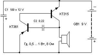
Transistors can be replaced with similar ones as in the previous circuit.
The total duration of the sound depends on capacity C1, and C2 determines the duration of pauses between “beats”. Sometimes, for a more believable sound, it is useful to select transistor VT1, since the operation of the simulator depends on its initial collector current and gain (h21e).
Engine sound simulator
They can, for example, voice a radio-controlled or other model of a mobile device.

Options for replacing transistors and speakers - as in previous schemes. Transformer T1 is the output from any small-sized radio receiver (a speaker is also connected through it in the receivers).
There are many schemes for simulating the sounds of birdsong, animal voices, steam locomotive whistles, etc. The circuit proposed below is assembled on just one digital chip K176LA7 (K561 LA7, 564LA7) and allows you to simulate many different sounds depending on the value of the resistance connected to the input contacts X1.

It should be noted that the microcircuit here operates “without power,” that is, no voltage is supplied to its positive terminal (pin 14). Although in fact the microcircuit is still powered, this happens only when a resistance sensor is connected to the X1 contacts. Each of the eight inputs of the chip is connected to the internal power bus through diodes that protect against static electricity or incorrect connections. The microcircuit is powered through these internal diodes due to the presence of positive power feedback through the input resistor-sensor.
The circuit consists of two multivibrators. The first (on elements DD1.1, DD1.2) immediately begins to generate rectangular pulses with a frequency of 1 ... 3 Hz, and the second (DD1.3, DD1.4) comes into operation when the logical level " 1". It produces tone pulses with a frequency of 200 ... 2000 Hz. From the output of the second multivibrator, pulses are supplied to the power amplifier (transistor VT1) and a modulated sound is heard from the dynamic head.
If you now connect a variable resistor with a resistance of up to 100 kOhm to the input jacks X1, then power feedback occurs and this transforms the monotonous intermittent sound. By moving the slider of this resistor and changing the resistance, you can achieve a sound reminiscent of the trill of a nightingale, the chirping of a sparrow, the quack of a duck, the croaking of a frog, etc.
Details
The transistor can be replaced with KT3107L, KT361G, but in this case you need to install R4 with a resistance of 3.3 kOhm, otherwise the sound volume will decrease. Capacitors and resistors - any type with ratings close to those indicated in the diagram. It must be borne in mind that the K176 series microcircuits of early releases do not have the above protective diodes and such copies will not work in this circuit! It’s easy to check the presence of internal diodes - just measure the resistance with a tester between pin 14 of the microcircuit (“+” power supply) and its input pins (or at least one of the inputs). As with diode testing, the resistance should be low in one direction and high in the other.
There is no need to use a power switch in this circuit, since in idle mode the device consumes a current of less than 1 µA, which is significantly less than even the self-discharge current of any battery!
Setup
A correctly assembled simulator does not require any adjustment. To change the tone of the sound, you can select capacitor C2 from 300 to 3000 pF and resistors R2, R3 from 50 to 470 kOhm.
Flashing light
The flashing frequency of the lamp can be adjusted by selecting elements R1, R2, C1. The lamp can be from a flashlight or a car 12 V. Depending on this, you need to select the supply voltage of the circuit (from 6 to 12 V) and the power of the switching transistor VT3.
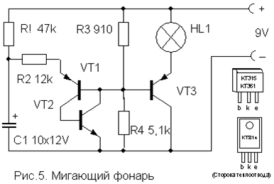
Transistors VT1, VT2 - any low-power corresponding structures (KT312, KT315, KT342, KT 503 (n-p-n) and KT361, KT645, KT502 (p-n-p), and VT3 - medium or high power (KT814, KT816, KT818).
A simple device for listening to the sound of TV broadcasts on headphones. Does not require any power and allows you to move freely within the room.

Coil L1 is a “loop” of 5...6 turns of PEV (PEL)-0.3...0.5 mm wire, laid around the perimeter of the room. It is connected in parallel to the TV speaker via switch SA1 as shown in the figure. For normal operation of the device, the output power of the TV audio channel must be within 2...4 W, and the loop resistance must be 4...8 Ohms. The wire can be laid under the baseboard or in the cable channel, and it should be located, if possible, no closer than 50 cm from the wires of the 220 V network to reduce alternating voltage interference.

The L2 coil is wound onto a frame made of thick cardboard or plastic in the form of a ring with a diameter of 15...18 cm, which serves as a headband. It contains 500...800 turns of PEV (PEL) wire 0.1...0.15 mm secured with glue or electrical tape. A miniature volume control R and an earphone (high-impedance, for example TON-2) are connected in series to the coil terminals.
Automatic light switch
This one differs from many circuits of similar machines in its extreme simplicity and reliability and does not need a detailed description. It allows you to turn on the lighting or some electrical appliance for a specified short time, and then automatically turns it off.

To turn on the load, just briefly press switch SA1 without latching. In this case, the capacitor manages to charge and opens the transistor, which controls the relay switching on. The turn-on time is determined by the capacitance of capacitor C and with the nominal value indicated in the diagram (4700 mF) it is about 4 minutes. An increase in the on-state time is achieved by connecting additional capacitors in parallel with C.
The transistor can be any n-p-n type of medium power or even low-power, such as KT315. This depends on the operating current of the relay used, which can also be any other with an operating voltage of 6-12 V and capable of switching the load of the power you need. You can also use p-n-p type transistors, but you will need to change the polarity of the supply voltage and turn on capacitor C. Resistor R also affects the response time within small limits and can be rated 15 ... 47 kOhm depending on the type of transistor.
List of radioelements
| Designation | Type | Denomination | Quantity | Note | Shop | My notepad | |
|---|---|---|---|---|---|---|---|
| Electronic duck | |||||||
| VT1, VT2 | Bipolar transistor | KT361B | 2 | MP39-MP42, KT209, KT502, KT814 | To notepad | ||
| HL1, HL2 | Light-emitting diode | AL307B | 2 | To notepad | |||
| C1 | 100uF 10V | 1 | To notepad | ||||
| C2 | Capacitor | 0.1 µF | 1 | To notepad | |||
| R1, R2 | Resistor | 100 kOhm | 2 | To notepad | |||
| R3 | Resistor | 620 Ohm | 1 | To notepad | |||
| BF1 | Acoustic emitter | TM2 | 1 | To notepad | |||
| SA1 | Reed switch | 1 | To notepad | ||||
| GB1 | Battery | 4.5-9V | 1 | To notepad | |||
| Simulator of the sound of a bouncing metal ball | |||||||
| Bipolar transistor | KT361B | 1 | To notepad | ||||
| Bipolar transistor | KT315B | 1 | To notepad | ||||
| C1 | Electrolytic capacitor | 100uF 12V | 1 | To notepad | |||
| C2 | Capacitor | 0.22 µF | 1 | To notepad | |||
| Dynamic head | GD 0.5...1W 8 Ohm | 1 | To notepad | ||||
| GB1 | Battery | 9 Volt | 1 | To notepad | |||
| Engine sound simulator | |||||||
| Bipolar transistor | KT315B | 1 | To notepad | ||||
| Bipolar transistor | KT361B | 1 | To notepad | ||||
| C1 | Electrolytic capacitor | 15uF 6V | 1 | To notepad | |||
| R1 | Variable resistor | 470 kOhm | 1 | To notepad | |||
| R2 | Resistor | 24 kOhm | 1 | To notepad | |||
| T1 | Transformer | 1 | From any small radio receiver | To notepad | |||
| Universal sound simulator | |||||||
| DD1 | Chip | K176LA7 | 1 | K561LA7, 564LA7 | To notepad | ||
| Bipolar transistor | KT3107K | 1 | KT3107L, KT361G | To notepad | |||
| C1 | Capacitor | 1 µF | 1 | To notepad | |||
| C2 | Capacitor | 1000 pF | 1 | To notepad | |||
| R1-R3 | Resistor | 330 kOhm | 1 | To notepad | |||
| R4 | Resistor | 10 kOhm | 1 | To notepad | |||
| Dynamic head | GD 0.1...0.5Watt 8 Ohm | 1 | To notepad | ||||
| GB1 | Battery | 4.5-9V | 1 | To notepad | |||
| Flashing light | |||||||
| VT1, VT2 | Bipolar transistor | ||||||
Learning to read electrical circuit diagrams
I already talked about how to read circuit diagrams in the first part. Now I would like to cover this topic more fully, so that even a beginner in electronics does not have questions. So, let's go. Let's start with the electrical connections.
It is no secret that in a circuit any radio component, for example a microcircuit, can be connected by a huge number of conductors to other elements of the circuit. In order to free up space on the circuit diagram and remove “repetitive connecting lines”, they are combined into a kind of “virtual” harness - they designate a group communication line. On the diagrams group line denoted as follows.

Here's an example.

As you can see, such a group line is thicker than other conductors in the circuit.
In order not to get confused where which conductors go, they are numbered.
In the figure I marked the connecting wire under the number 8 . It connects pin 30 of the DD2 chip and 8 XP5 connector pin. In addition, pay attention to where the 4th wire goes. For the XP5 connector, it is connected not to pin 2 of the connector, but to pin 1, which is why it is indicated on the right side of the connecting conductor. The 5th conductor is connected to the 2nd pin of the XP5 connector, which comes from the 33rd pin of the DD2 chip. I note that the connecting conductors with different numbers are not electrically connected to each other, and on a real printed circuit board they can be located in different parts of the board.
The electronic content of many devices consists of blocks. And, therefore, detachable connections are used to connect them. This is how detachable connections are indicated on the diagrams.

XP1 - this is a fork (aka "Dad"), XS1 - this is a socket (aka “Mom”). All together this is “Papa-Mama” or connector X1 (X2 ).
Electronic devices may also contain mechanically coupled elements. Let me explain what we are talking about.
For example, there are variable resistors that have a built-in switch. I talked about one of these in the article about variable resistors. This is how they are indicated on the circuit diagram. Where SA1 - a switch, and R1 - variable resistor. The dotted line indicates the mechanical connection of these elements.

Previously, such variable resistors were very often used in portable radios. When we turned the volume control knob (our variable resistor), the contacts of the built-in switch first closed. Thus, we turned on the receiver and immediately adjusted the volume with the same knob. I note that the variable resistor and switch do not have electrical contact. They are only connected mechanically.
The same situation is with electromagnetic relays. The relay coil itself and its contacts do not have an electrical connection, but they are mechanically connected. We apply current to the relay winding - the contacts close or open.

Since the control part (relay winding) and the executive part (relay contacts) can be separated on the circuit diagram, their connection is indicated by a dotted line. Sometimes the dotted line don't draw at all, and the contacts simply indicate their belonging to the relay ( K1.1) and contact group number (K1. 1 ) and (K1. 2 ).
Another fairly clear example is the volume control of a stereo amplifier. To adjust the volume, two variable resistors are required. But adjusting the volume in each channel separately is impractical. Therefore, dual variable resistors are used, where two variable resistors have one control shaft. Here is an example from a real circuit.

In the figure, I highlighted two parallel lines in red - they indicate the mechanical connection of these resistors, namely that they have one common control shaft. You may have already noticed that these resistors have a special position designation R4. 1 and R4. 2 . Where R4 - this is the resistor and its serial number in the circuit, and 1 And 2 indicate sections of this dual resistor.
Also, the mechanical connection of two or more variable resistors can be indicated by a dotted line rather than two solid ones.

I note that electrically these variable resistors have no contact between themselves. Their terminals can only be connected in a circuit.
It is no secret that many radio equipment components are sensitive to the effects of external or “neighboring” electromagnetic fields. This is especially true in transceiver equipment. To protect such units from unwanted electromagnetic influences, they are placed in a screen and shielded. As a rule, the screen is connected to the common wire of the circuit. This is shown in the diagrams like this.

The contour is screened here 1T1 , and the screen itself is depicted by a dash-dotted line, which is connected to a common wire. The shielding material can be aluminum, metal casing, foil, copper plate, etc.
This is how shielded communication lines are designated. The figure in the lower right corner shows a group of three shielded conductors.

Coaxial cable is also designated in a similar way. Here's a look at its designation.
In reality, a shielded wire (coaxial) is an insulated conductor that is externally covered or wrapped with a shield of conductive material. This may be copper braiding or foil covering. The screen, as a rule, is connected to a common wire and thereby removes electromagnetic interference and interference.
Repeating elements.
There are often cases when absolutely identical elements are used in an electronic device and it is inappropriate to clutter the circuit diagram with them. Here, take a look at this example.

Here we see that the circuit contains resistors R8 - R15 of the same rating and power. Only 8 pieces. Each of them connects the corresponding pin of the microcircuit and a four-digit seven-segment indicator. In order not to indicate these repeating resistors on the diagram, they were simply replaced with bold dots.
One more example. Crossover (filter) circuit for an acoustic speaker. Pay attention to how instead of three identical capacitors C1 - C3, only one capacitor is indicated on the diagram, and the number of these capacitors is marked next to it. As can be seen from the diagram, these capacitors must be connected in parallel to obtain a total capacitance of 3 μF.

Likewise with capacitors C6 - C15 (10 µF) and C16 - C18 (11.7 µF). They must be connected in parallel and installed in place of the indicated capacitors.
It should be noted that the rules for designating radio components and elements on diagrams in foreign documentation are somewhat different. But, it will be much easier for a person who has received at least basic knowledge on this topic to understand them.